With a lot of people locked into their house most of the time I thought it was a good idea to publish this DIY hangboard for climbers and boulderers. It’s cheap and easy to build.
Category: woodworking
Categories
DIY Lego Cabinet
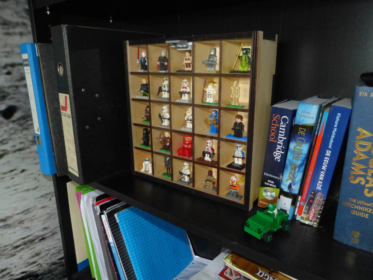
Making a woorden Lego cabinet for all this minifigs is easy and cheap. You do need a laser cutter for this project.
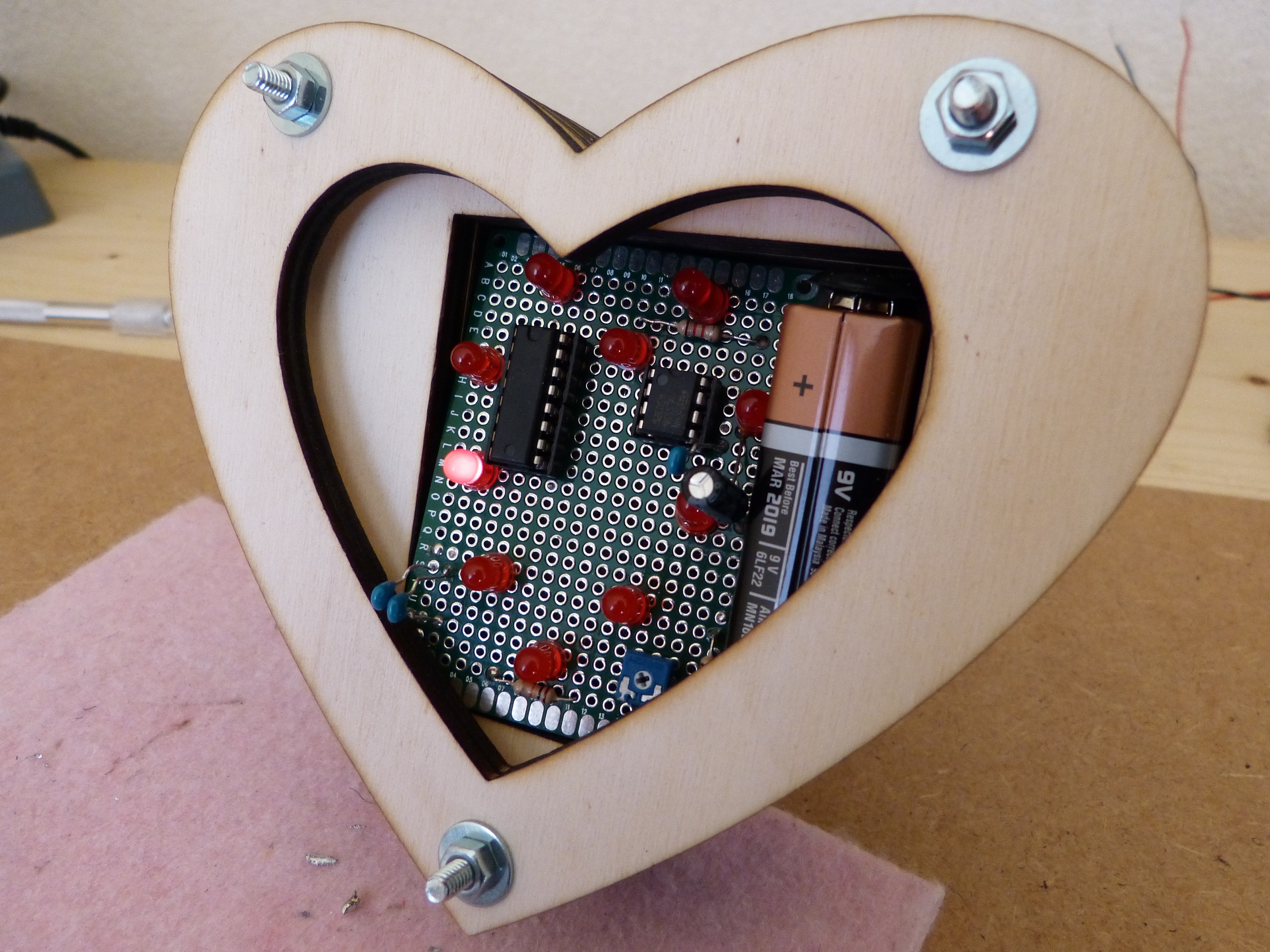
Looking for an idea for Valentine’s day. Look no further.
This is the last of a series of five where I design and build a Darth Vader chest box with the HT8950A chip. The series involves all the instructions for the electronics, laser cutting and a bit of 3d printing.
You can never have enough space
Categories
Homemade desk of scaffolding wood
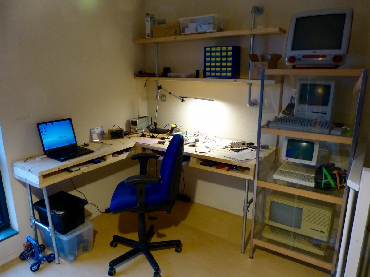
I made a L-shape desk of scaffolding wood and galvanised pipes.
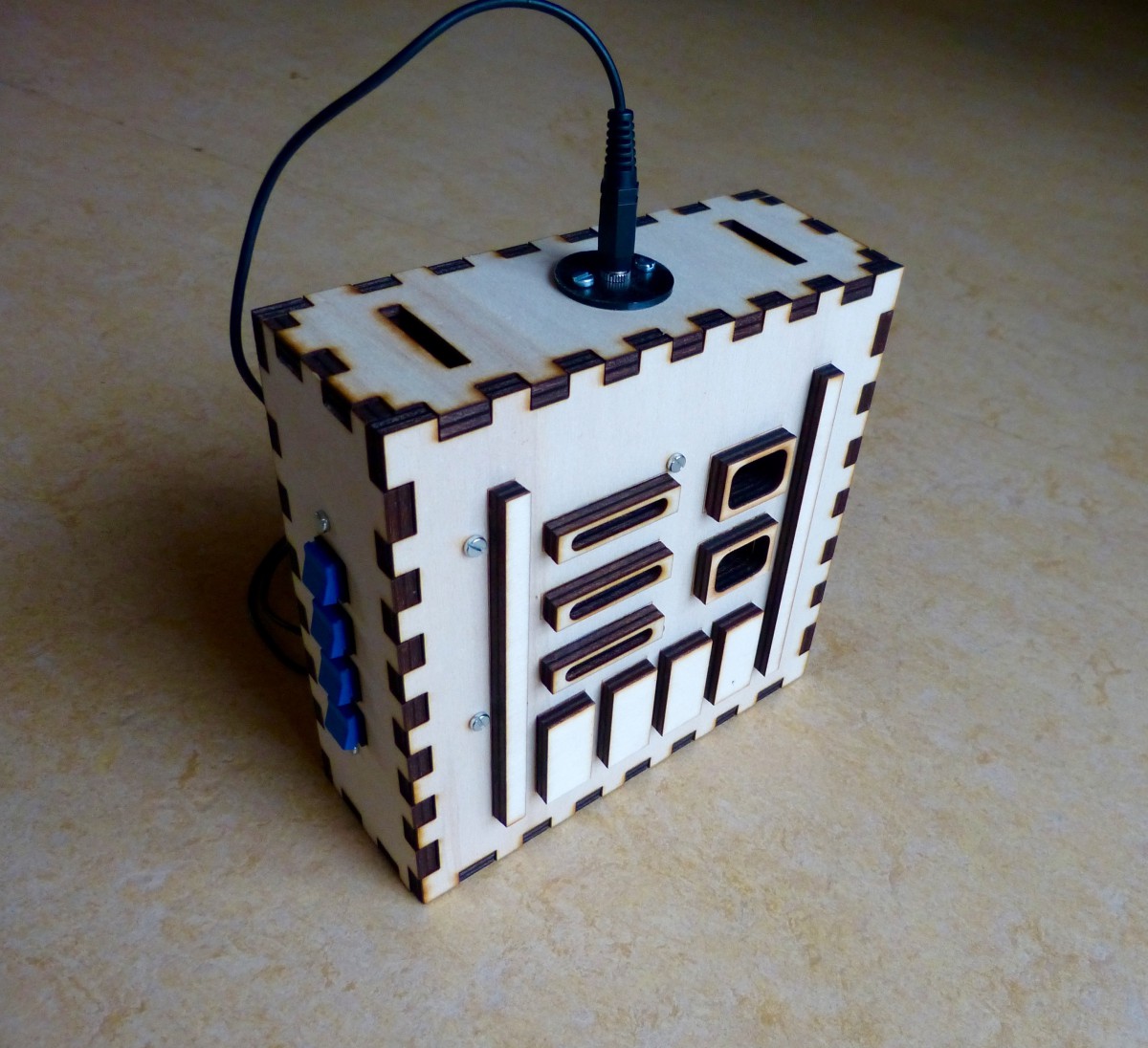
This is the third of a series of five where I design and build a Darth Vader chest box with the HT8950A chip. The series involves all the instructions for the electronics, laser cutting and a bit of 3d printing.
This is the second of a series of five where I design and build a Darth Vader chest box with the HT8950A chip. The series involves all the instructions for the electronics, laser cutting and a bit of 3d printing.
In the last two weeks I have built a Raspberry Pi surveillance camera. For the time being I used a crude housing made out of MDF. This was ok for testing purposes but now I wanted something more permanent. Something that I could attach to my window frame and that is able to pan and […]
Categories
Homemade camera dolly
Finished camera dolly made out of Makeblock and plywood. The plywood is painted black with a regular (alkyd) spray paint. I make a lot of video’s of our projects so I figured a camera dolly would be a nice addition. I could buy one of course but making one is a lot more fun. About […]