Using a Raspberry Pi and the program MPD to enhance my audio cooler
Using a Raspberry Pi and the program MPD to enhance my audio cooler
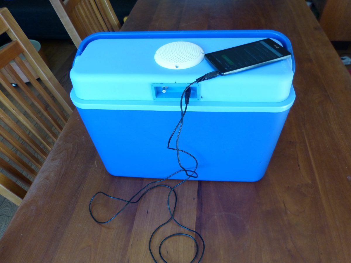
A made a 3d printed enclosure for the audio components that fits in the coolers lid together with a simple console to operate the audio
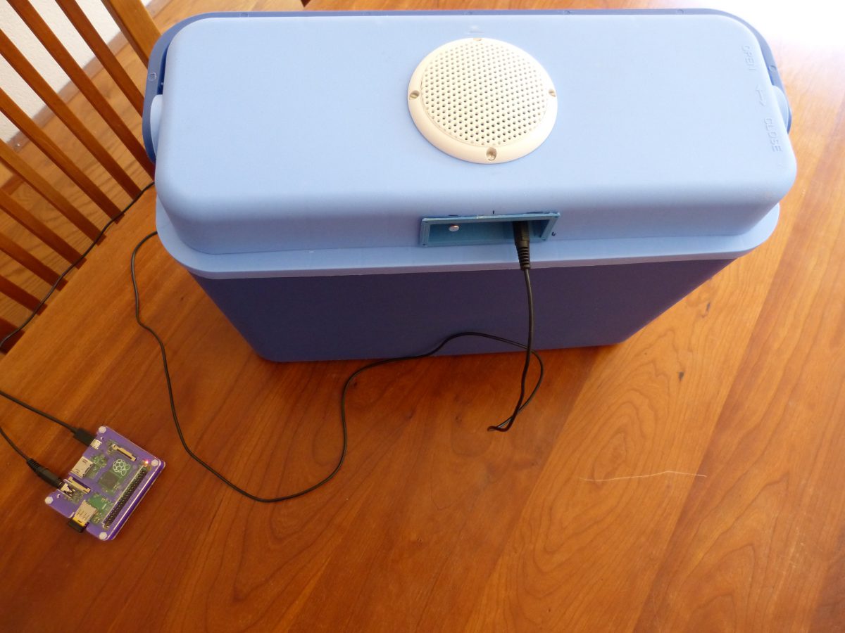
I’m selecting components for the audio cooler that I’m going to build. The components need to be tiny to fit in the coolers lid
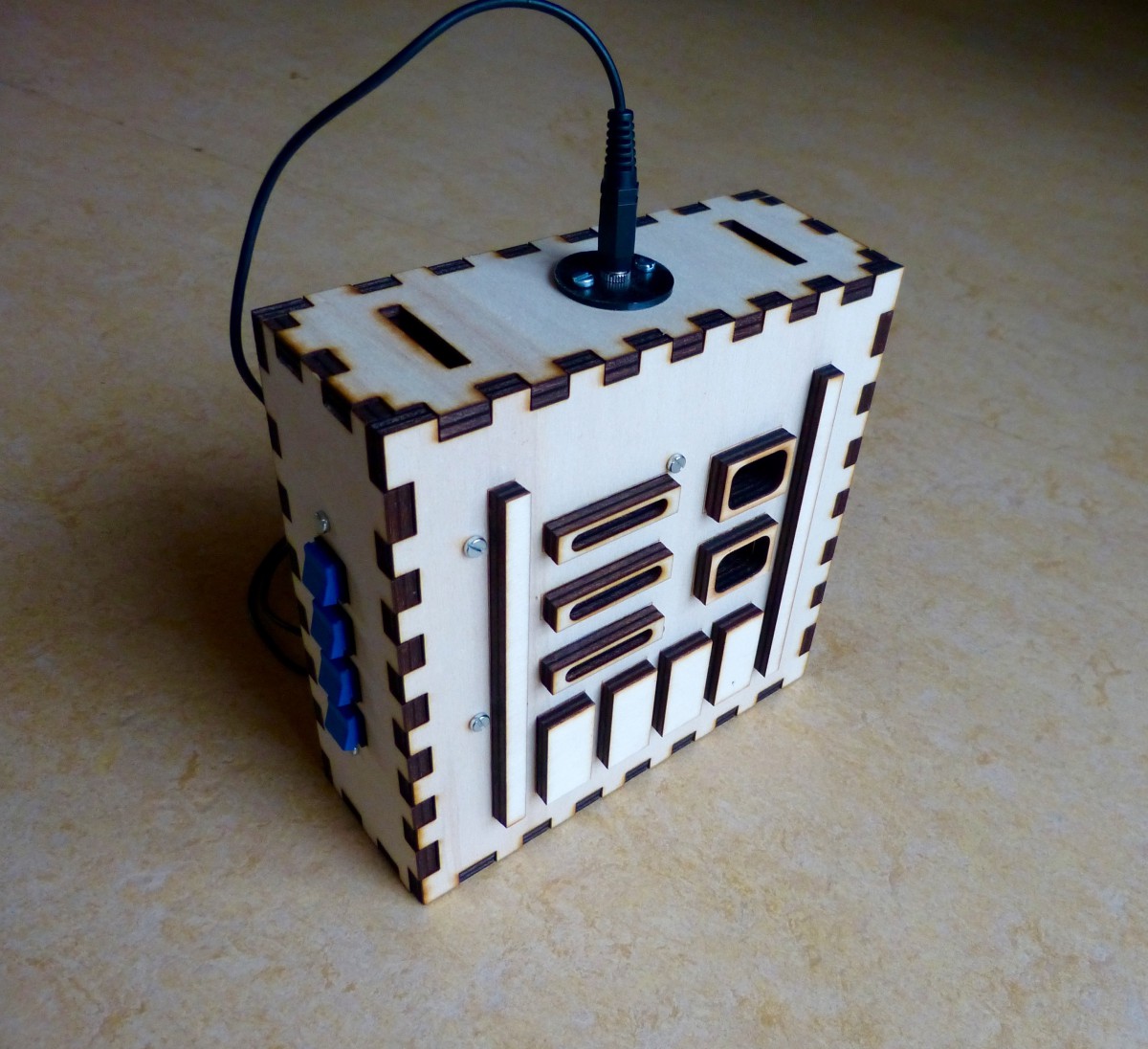
This is the last of a series of five where I design and build a Darth Vader chest box with the HT8950A chip. The series involves all the instructions for the electronics, laser cutting and a bit of 3d printing.
This is the fourth of a series of five where I design and build a Darth Vader chest box with the HT8950A chip. The series involves all the instructions for the electronics, laser cutting and a bit of 3d printing.
This is the third of a series of five where I design and build a Darth Vader chest box with the HT8950A chip. The series involves all the instructions for the electronics, laser cutting and a bit of 3d printing.
I finally finished the Darth Vader voice changer this weekend. I took a belt with two snap hooks from an old bag. Next I fitted the box with the voice changer with two black screw eyes that were large enough for the snap hooks. The enclosure is now comfortable around the neck of a child. […]
About a week ago I wrote about a Darth Vader voice changer that I am making. I finally have finished a prototype but not without problem. I soldered all the external components to the Velleman MK171 kit. When I tested the circuit I discovered that three red push-buttons (see images below) weren’t functioning. I disconnected […]
First part in a series how to make a Darth Vader voice changer with the HT8950 chip.
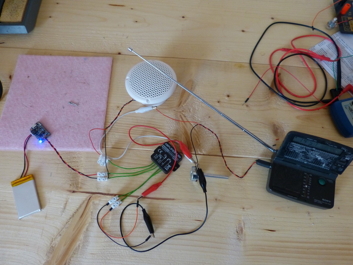
Begin this week I created a simple Audio Amplifier with the LM386 (see previous entry). I noted that there was some noise coming from the speakers. I already had a 100uF capacitor on the breadboard to smoothen the power fluctuations. I searched the internet for solutions to further reduce the noise. I found three possible […]