I’ve created an OpenSCAD script that generates Truchet tiles. Truchet tiles are square tiles decorated with patterns that are not rotationally symmetric. When placed in a square tiling of the plane, they can form varied patterns. The original Truchet tiles stem from a paper published in 1704 written by a french monk Sebastian Truchet. The […]
Category: 3d printing
I just uploaded a video here about Spiral Phyllotaxis patterns in OpenSCAD. The video, originally posted by me on YouTube some years ago, is about a script that I made to demonstrate Spiral Phyllotaxis. Phyllotaxis is a term used for patterns that emerge during the growth of plants. Spiral Phyllotaxis is observed in the heads […]
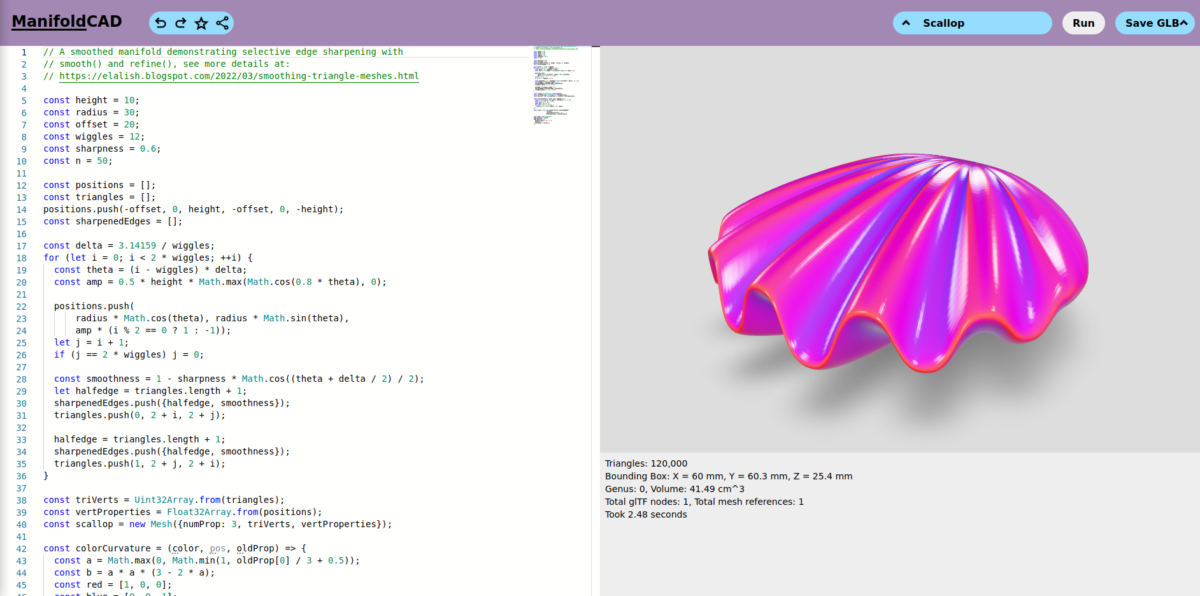
I’ve been taking a brief look at ManifoldCAD, a 3DCAD program in the style of OpenSCAD that runs in the browser and uses Javascript. ManifoldCAD is a relative new project from Emmet Lalish. It’s free and open source software (Apache-2.0 license). In case you are not familiar with these kind of CAD programs, instead of […]
In this blog post I’ll continue a previous post about polyhedron in OpenSCAD. Now we create something more exiting, a twisted vase.
Create a lithophane from your own photo using the Customizer of OpenSCAD.
Creating a 3d printable lithophane in OpenSCAD is relatively easy. But in this post we use a trick to create a curved lithophane.
I found an example on Thingiverse, a rubber band powered boat with two peddle wheels, but it has two problems. First of all the author only provides .stl files and second the design is a bit flawed. I therefore decided to design the boat from scratch with the 3d CAD program OpenSCAD. With OpenSCAD I’m […]
Parametric design of a simple hook in, the free and open source, OpenSCAD. Use with the Customizer in OpenSCAD
In this Solvespace new series of video tutorials I’ll demonstrate how to create an involute gear, adjust an existing involute gear and demonstrate how one involute gear drives another.
I uploaded my sixth remastered Solvespace video to PeerTube.