Using a Raspberry Pi and the program MPD to enhance my audio cooler
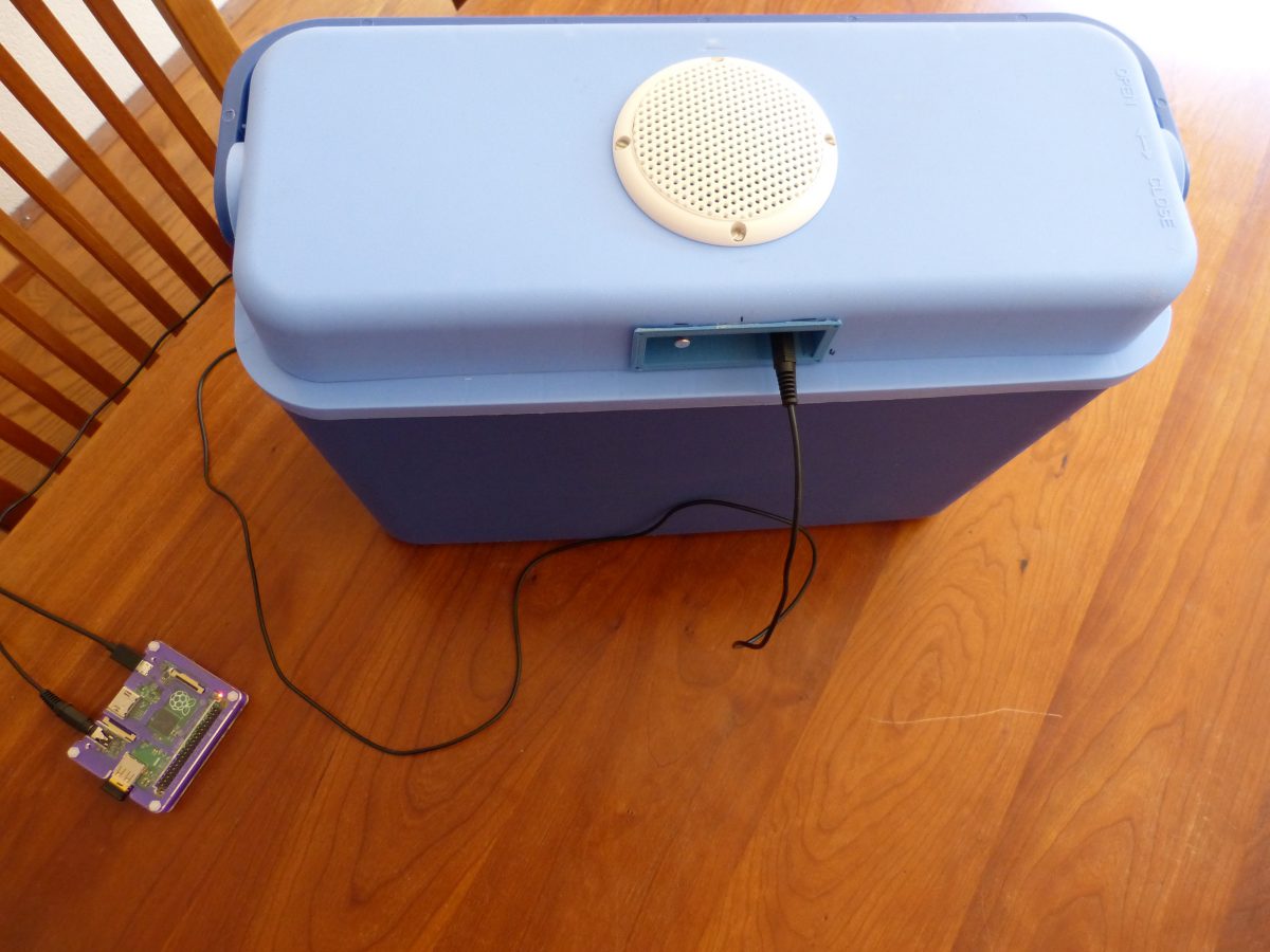
Using a Raspberry Pi and the program MPD to enhance my audio cooler
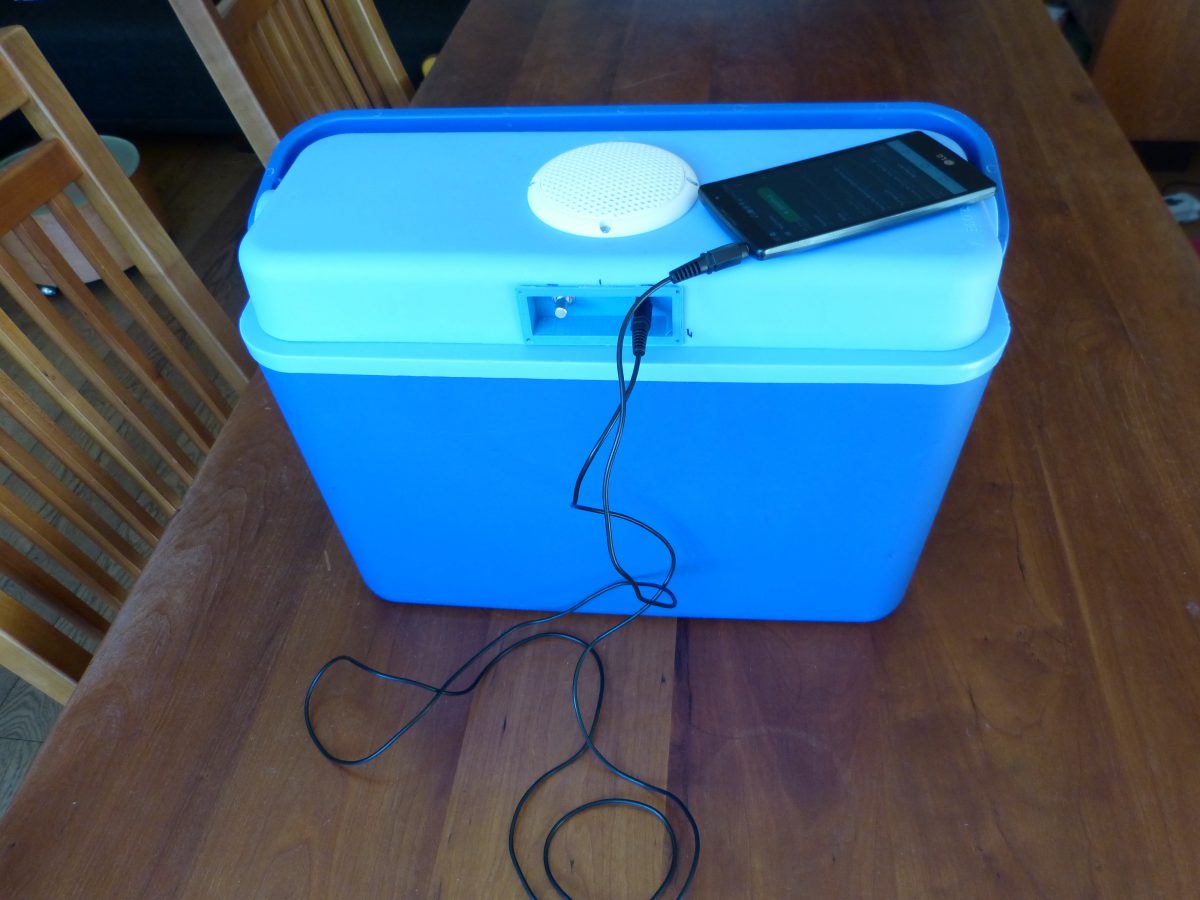
A made a 3d printed enclosure for the audio components that fits in the coolers lid together with a simple console to operate the audio
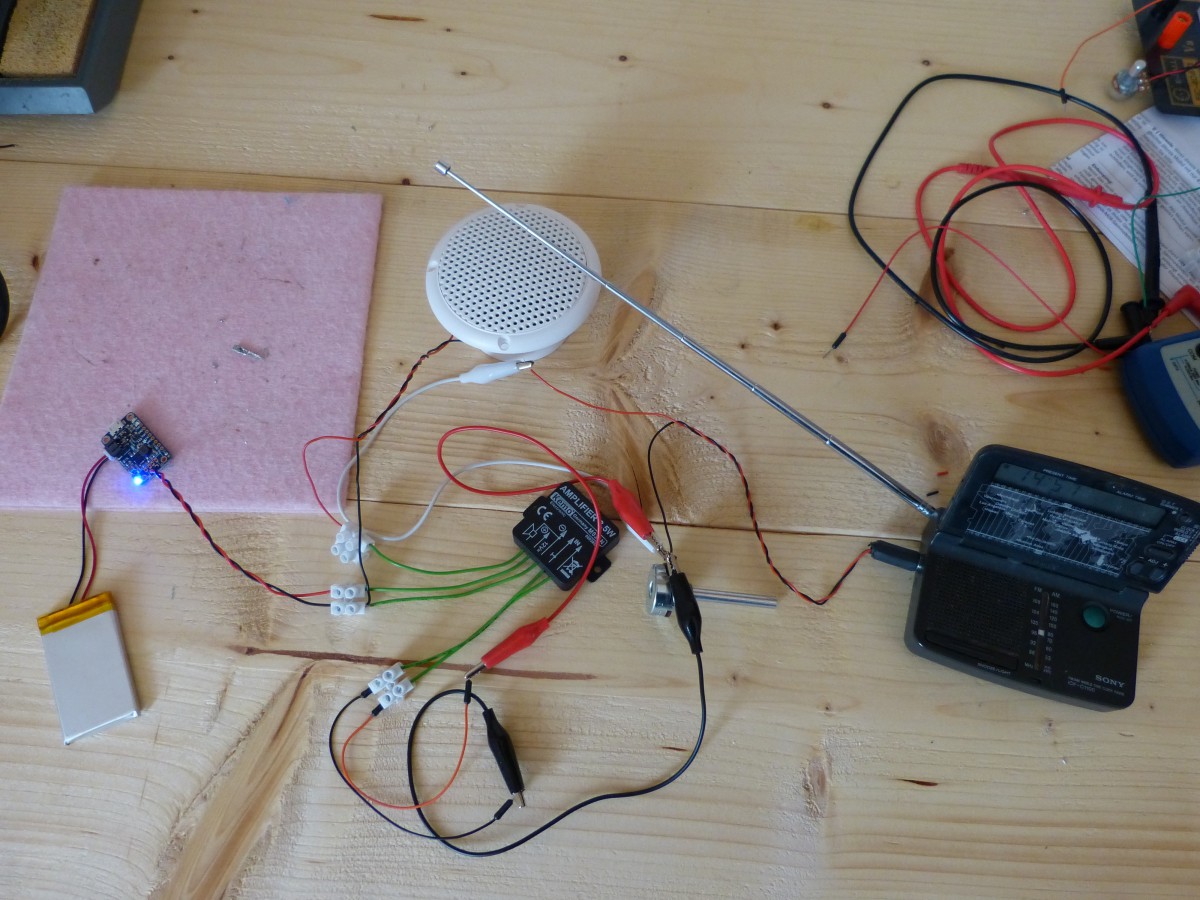
I’m selecting components for the audio cooler that I’m going to build. The components need to be tiny to fit in the coolers lid
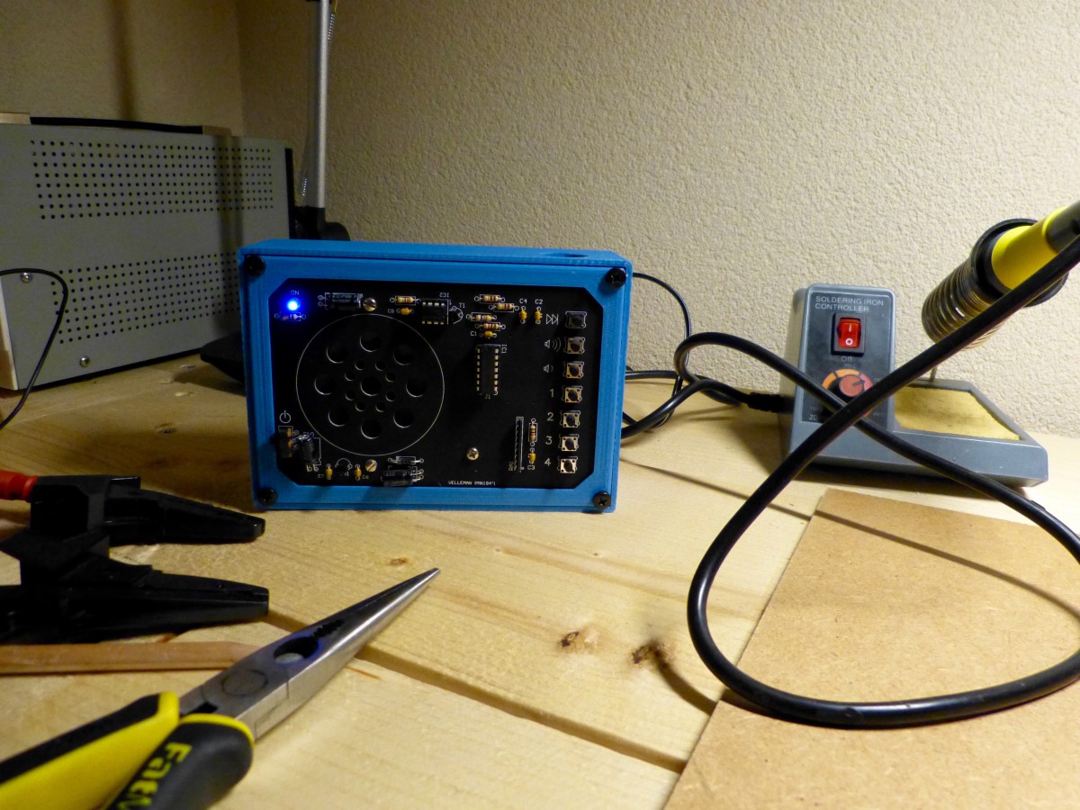
Making good use of a 3d printer
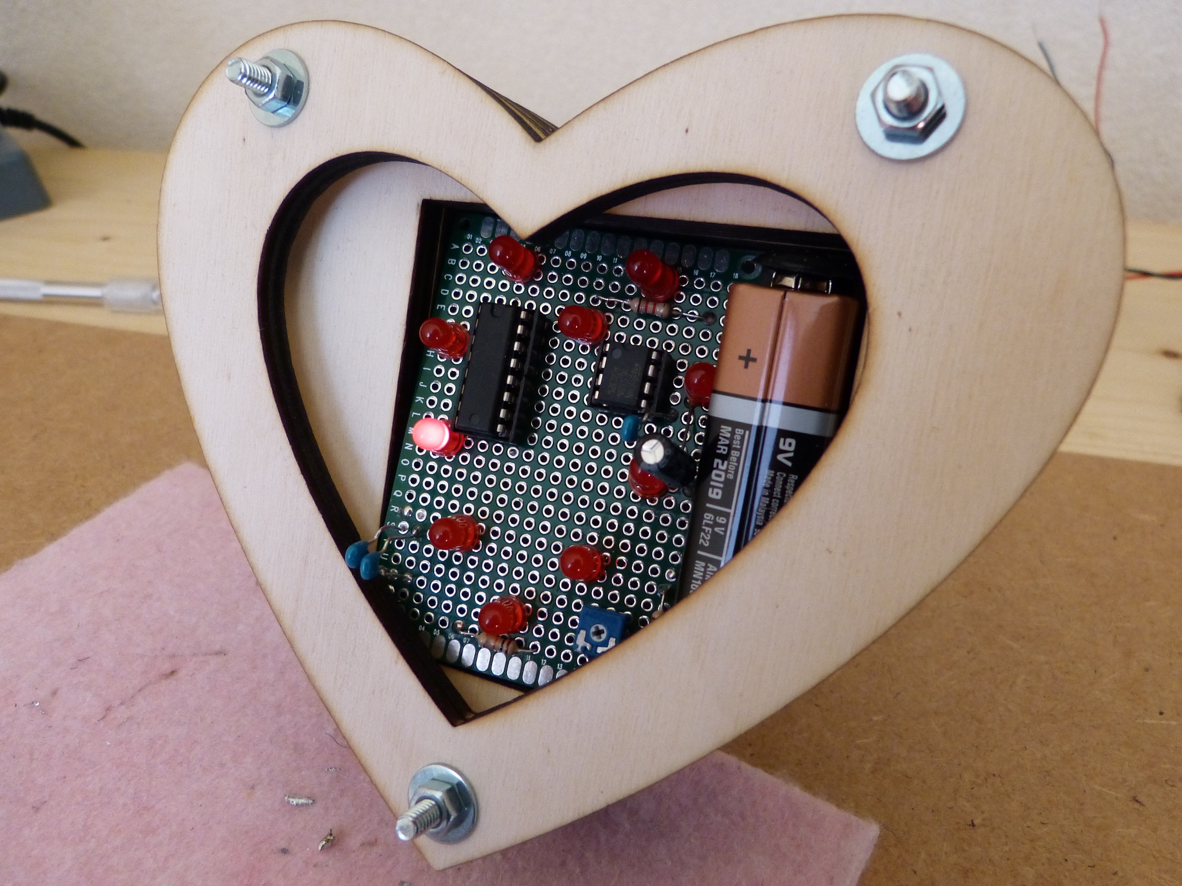
Looking for an idea for Valentine’s day. Look no further.
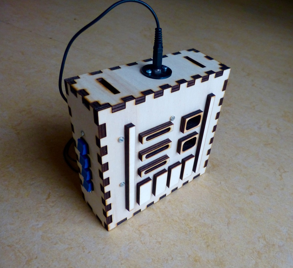
This is the last of a series of five where I design and build a Darth Vader chest box with the HT8950A chip. The series involves all the instructions for the electronics, laser cutting and a bit of 3d printing.
This is the fourth of a series of five where I design and build a Darth Vader chest box with the HT8950A chip. The series involves all the instructions for the electronics, laser cutting and a bit of 3d printing.
This is the third of a series of five where I design and build a Darth Vader chest box with the HT8950A chip. The series involves all the instructions for the electronics, laser cutting and a bit of 3d printing.
This is the first of a series of five where I design and build a Darth Vader chest box with the HT8950A chip. The series involves all the instructions for the electronics, laser cutting and a bit of 3d printing.
In my previous post about the robot cart I described how I finished the cart and tested the circuit on the breadboard. I only had to solder the circuit to the perf board and mount the board on the cart. Simple, right. Unfortunately it wasn’t that simple. After soldering I tested the board and discovered […]