Introduction
The last month I’ve been working on my Darth Vader chest box. I’ve designed and built my own circuit with the Holtek HT8950A voice modulator. I create a laser cut case and designed 3D printed parts for the chest box. Since I had to learn a lot of new techniques, e.g laser cutting and 3D printing, this is by no means an easy project for me. With the project in its final stages now some design problems turn up that need fixing.
Soldering the board.
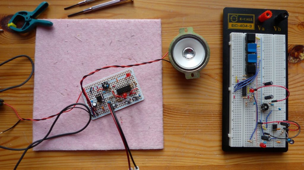
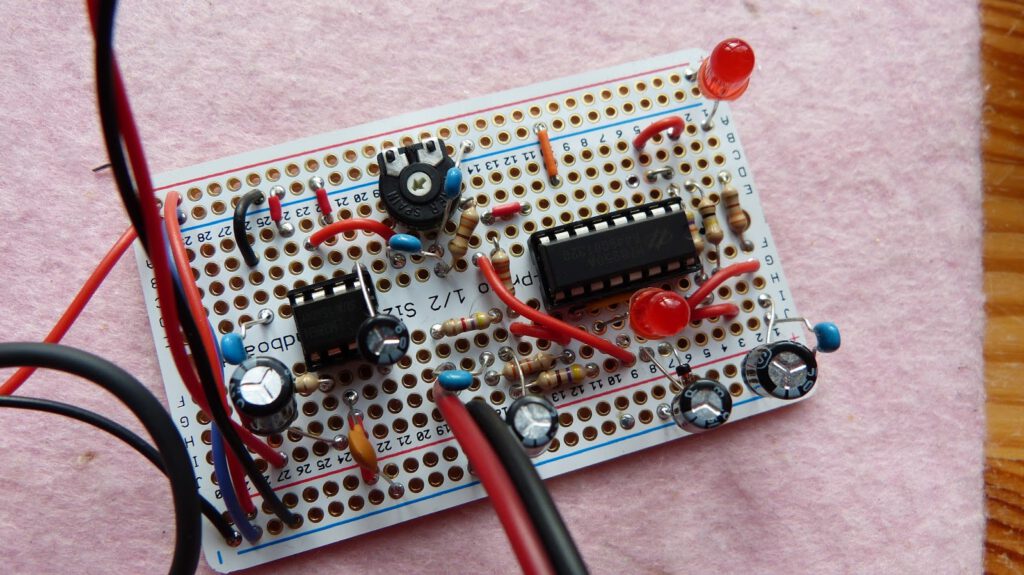
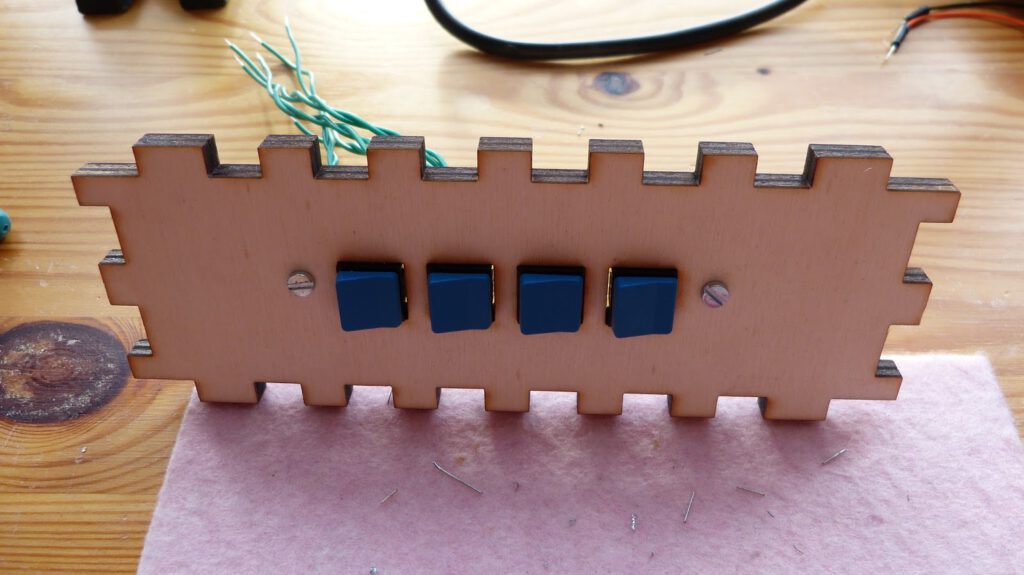
This week I soldered the components to the board. First I soldered the voice changer components and made sure this part of the circuit is working. Next I soldered the amplifier. I tested the total circuit and it worked the first time which is always a joyful moment. I find the Adafruit perma-protoboard very easy to work with since I’m able to copy the layout from the breadboard. Next I grouped all the buttons that operate the HT8950A on a board and soldered them to a piece perfboard. The buttons on the perfboard fit nicely into the laser cut side panel that I already made. Operating the chest box is easy with this (a major issue with my previous chest box).


Design issues
Last week I made 3D printed parts for the front of the chest box. Unfortunately I found that these parts didn’t look good with the laser cut box. The plastic parts just didn’t do justice to the laser cut plywood. I therefore decided to laser cut all the parts that sit on the from of the box with I think is aesthetically more pleasing.
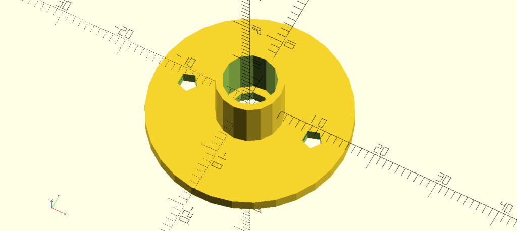
Another problem arose with the female audio jack connector that I need to plug in the microphone. The thread of this 3.5mm connector just isn’t long enough to be fitted onto the 6mm thick plywood. I designed a container to solve this. The audio connector fits into this container and the container is screwed to the case. The .stl file can be downloaded here: https://my.hidrive.com/lnk/RKCIiaQ2. Hopefully this container solves the problem.

Yet unsolved problems
- I need to attach a nylon belt to the chest box. I’m thinking about popper snap fasteners attached to the belt to open or close the belt.
- The HT8950A works fine with a proper audio signal as input but the microphone that I have, a small electret microphone, doesn’t give any audible output (except for noise). I assume that the signal is too weak and therefore needs amplification.
Here are the links to all blog posts I wrote about this chest box:
- Darth Vader voice changer 2.0 (HT8950A) part 1, demonstrates the voice changer on the breadboard: https://homehack.nl/darth-vader-voice-changer-2-0-ht8950a/
- Darth Vader voice changer 2.0 part 2: designing the case: https://homehack.nl/darth-vader-voice-changer-2-0-designing-the-case/
- Homemade Darth Vader Voice Changer 2.0 (work in progress) part 3: https://homehack.nl/homemade-darth-vader-voice-changer-2-0-work-in-progress/
- The Darth Vader chest box part 4: almost finished: https://homehack.nl/the-darth-vader-chest-box-is-almost-finished
- Darth Vader voice changer 2.0 part 5: finished: https://homehack.nl/darth-vader-chest-box-finished/
Thanks for reading!
One reply on “Darth Vader voice changer 2.0 part 4: almost finished”
Hoi,
ik denk dat ik de oplossing weet voor je Darth Vader microfoon probleem.
Je schrijft dat je een elctret condenser microfoon gebruikt. Ik vermoed dat je een true condenser microfoon moet gebruikt. Dus zo eentje waar een batterij in hoort.