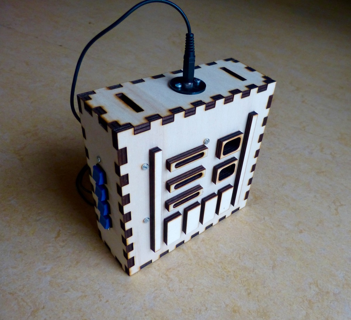
This is the last of a series of five where I design and build a Darth Vader chest box with the HT8950A chip. The series involves all the instructions for the electronics, laser cutting and a bit of 3d printing.


This is the last of a series of five where I design and build a Darth Vader chest box with the HT8950A chip. The series involves all the instructions for the electronics, laser cutting and a bit of 3d printing.
This is the fourth of a series of five where I design and build a Darth Vader chest box with the HT8950A chip. The series involves all the instructions for the electronics, laser cutting and a bit of 3d printing.
This is the third of a series of five where I design and build a Darth Vader chest box with the HT8950A chip. The series involves all the instructions for the electronics, laser cutting and a bit of 3d printing.
This is the second of a series of five where I design and build a Darth Vader chest box with the HT8950A chip. The series involves all the instructions for the electronics, laser cutting and a bit of 3d printing.
This is the first of a series of five where I design and build a Darth Vader chest box with the HT8950A chip. The series involves all the instructions for the electronics, laser cutting and a bit of 3d printing.
In my previous post about the robot cart I described how I finished the cart and tested the circuit on the breadboard. I only had to solder the circuit to the perf board and mount the board on the cart. Simple, right. Unfortunately it wasn’t that simple. After soldering I tested the board and discovered […]
This experiment is about building a little robot cart. Make:Electronics describes all the steps that needs to be taken in great detail beginning with the cart and then the circuit. This experiment is a lot of work but I think it is worth it because you make a complete robot from the bottom up. The cart […]
During experiment 29 and 30 of Make:Electronics I noticed that the circuit was very susceptible to noise to the point that it really interfered with the experiments. While thinking about it I suspected that something was wrong with the breadboard. I decided to redo both experiments with a another breadboard (but without the low pass […]
After some refurbishing around the house I’m finally back with Make:Electronics. In experiment 30 I used most of the circuitry from experiment 29. The idea is to create a distorted sound. The base of an NPN transitor receives the output from the 555 timer thus controlling the base of another NPN transistor (see fig 5-55 […]
I finally reached the second stage of Experiment 29 of Make: Electronics. In the first stage I used an audio amplifier (TEA2025B) and a coil to create a crossover network. During this first stage the source of the audio was an iPod (read here). In the second stage the iPod was replaced by a 555 […]