After some refurbishing around the house I’m finally back with Make:Electronics. In experiment 30 I used most of the circuitry from experiment 29. The idea is to create a distorted sound. The base of an NPN transitor receives the output from the 555 timer thus controlling the base of another NPN transistor (see fig 5-55 of the book). The base (not the emitter since amplification is not needed) of this second transistor controls the amplifier (TEA2025B). The input of the amplifier is overloaded thereby creating a distorted sound (fuzz)
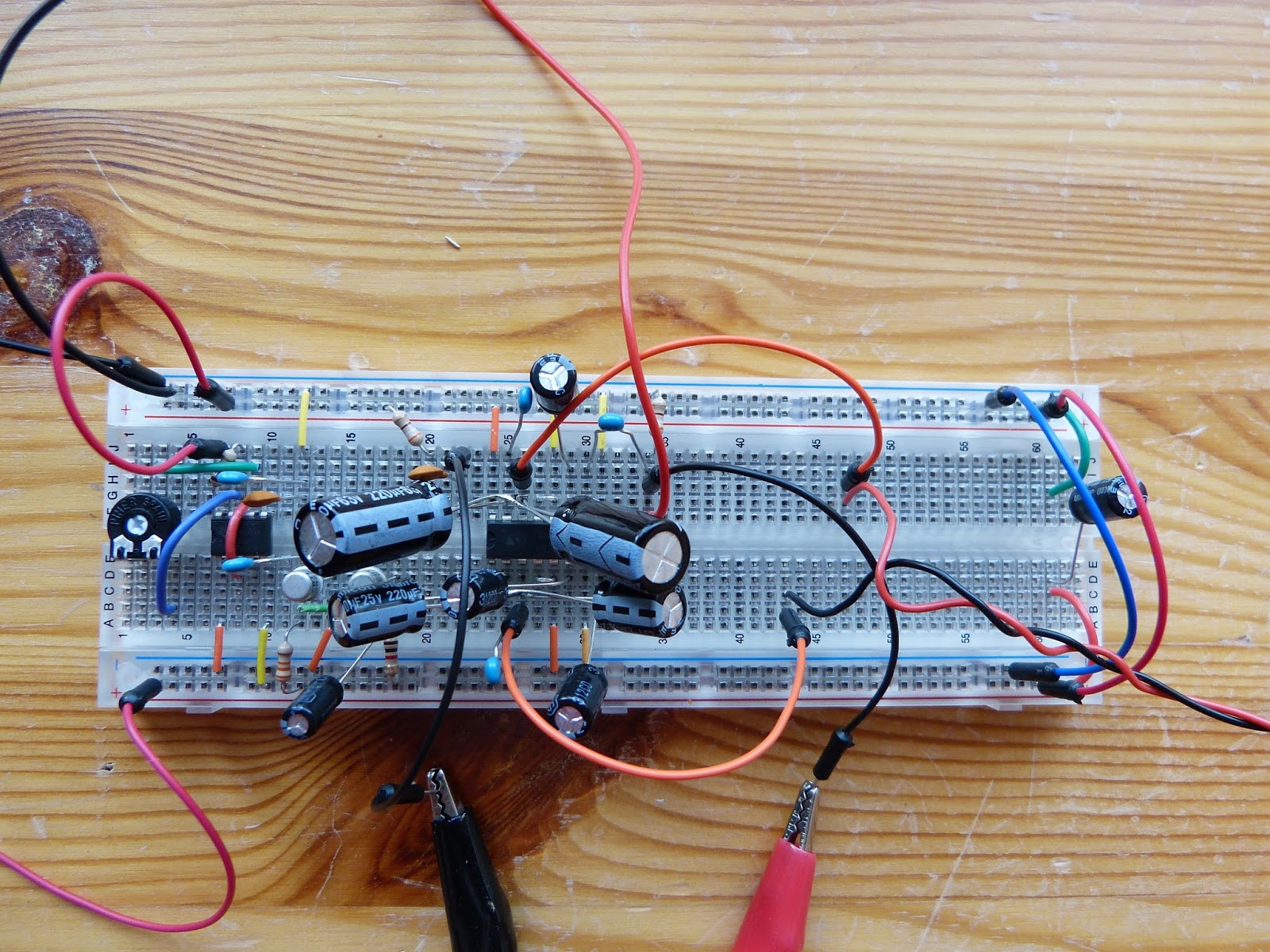
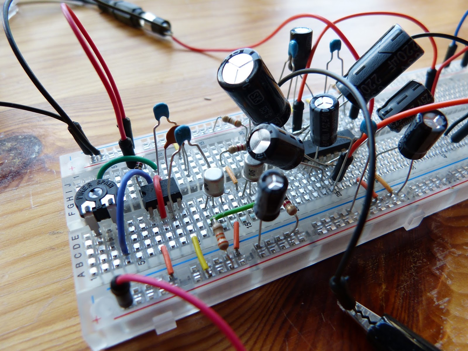
Building the circuit is easy enough since I could use most of the circuit from experiment 29. The most important change, besides some resistors and capacitors, is the addition of two 2N2222 transistors. For the output adjustment of the transistors I used a 50K potentiometer instead of a 100K. Trouble began when I tested the circuit. Amplification of the audio input worked fine (although the circuit is susceptible to noise) however I couldn’t get the distortion to work. I determined that the 555 chip was working fine but couldn’t get a signal on the base of the first transistor. I switched the two transistors with each other to no avail (these are the last in my stock).
When I came back to the circuit a little later I noticed that the voltage was very low (about 5V). I had done that on purpose when I initially tested the circuit not wanting to overheat the amplifier but I hadn’t increased it afterwards. I increased the voltage to the required 9V and suddenly I had a beautiful harsh distortion coming out of my speaker (which annoyed my oldest son slightly since he was doing homework on the same floor). Next I’ll play around with some capacitors and resistors to change the distortion effect.
Thanks for reading!