I just uploaded a video here about Spiral Phyllotaxis patterns in OpenSCAD. The video, originally posted by me on YouTube some years ago, is about a script that I made to demonstrate Spiral Phyllotaxis. Phyllotaxis is a term used for patterns that emerge during the growth of plants. Spiral Phyllotaxis is observed in the heads […]
Category: programming
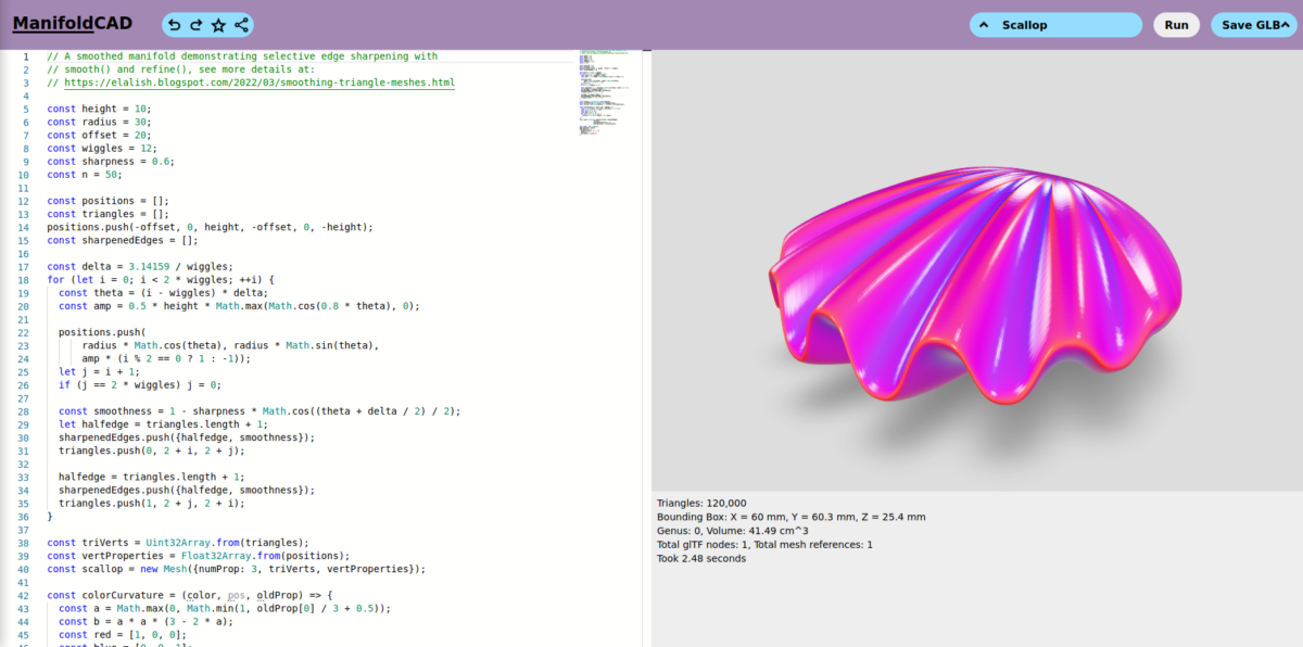
I’ve been taking a brief look at ManifoldCAD, a 3DCAD program in the style of OpenSCAD that runs in the browser and uses Javascript. ManifoldCAD is a relative new project from Emmet Lalish. It’s free and open source software (Apache-2.0 license). In case you are not familiar with these kind of CAD programs, instead of […]
I found an example on Thingiverse, a rubber band powered boat with two peddle wheels, but it has two problems. First of all the author only provides .stl files and second the design is a bit flawed. I therefore decided to design the boat from scratch with the 3d CAD program OpenSCAD. With OpenSCAD I’m […]
Parametric design of a simple hook in, the free and open source, OpenSCAD. Use with the Customizer in OpenSCAD
OpenSCAD allows the user to create complex shapes with the polygon function for 2D and polyhedron for 3D. Polygon and polyhedron both accept a list of 2D and 3D coordinates (points) respectively as parameters. A functions can generate a list of points eliminating the need to manually created these lists. This property can be used […]
In Part III of my Bash scripting adventures I’ll write a script rename all .jpg files in a folder.
In Part II of my Bash scripting adventures I’ll write a script to resize an image.
Categories
Humble start with Bash scripting
2019 is a good year to start scripting with Bash