OpenSCAD allows the user to create complex shapes with the polygon function for 2D and polyhedron for 3D. Polygon and polyhedron both accept a list of 2D and 3D coordinates (points) respectively as parameters. A functions can generate a list of points eliminating the need to manually created these lists. This property can be used to create shapes that are impossible with the 2D and 3D shapes that are build-in in OpenSCAD. In this blog post I’ll show how to create some simple 2D and 3D shapes and explain how to create more complex shapes.
Creating a 2D shape
To create a circle with a radius of 20 in OpenSCAD we just have to type
circle(20);However OpenSCAD doesn’t allow us to reshape this build-in function to for instance an ellipse. Alternatively we can write a function that generates a list of points needed for a circle and then use polygon with the points as parameter to draw the circle. The function uses the trigonometric formulas, x = r cos φ and y = sin φ, to convert polar coordinates to Cartesian coordinates.
function circle(radius) = [for (phi = [1 : 1 : 360]) [radius * cos(phi), radius * sin(phi)]];
polygon(circle(20));
When F5 is pressed a circle is drawn however the x,y coordinates of this circle are available to us. By adding echo(circle(20)); to our script the list of points is printed in the console. The circle function can easily be altered thus gaining a new shape. An example is shown below.
function circle(radius) = [for (phi = [0 : 1 : 720]) [radius * cos(phi/2), radius * sin(phi)]];
color("red") polygon(circle(20));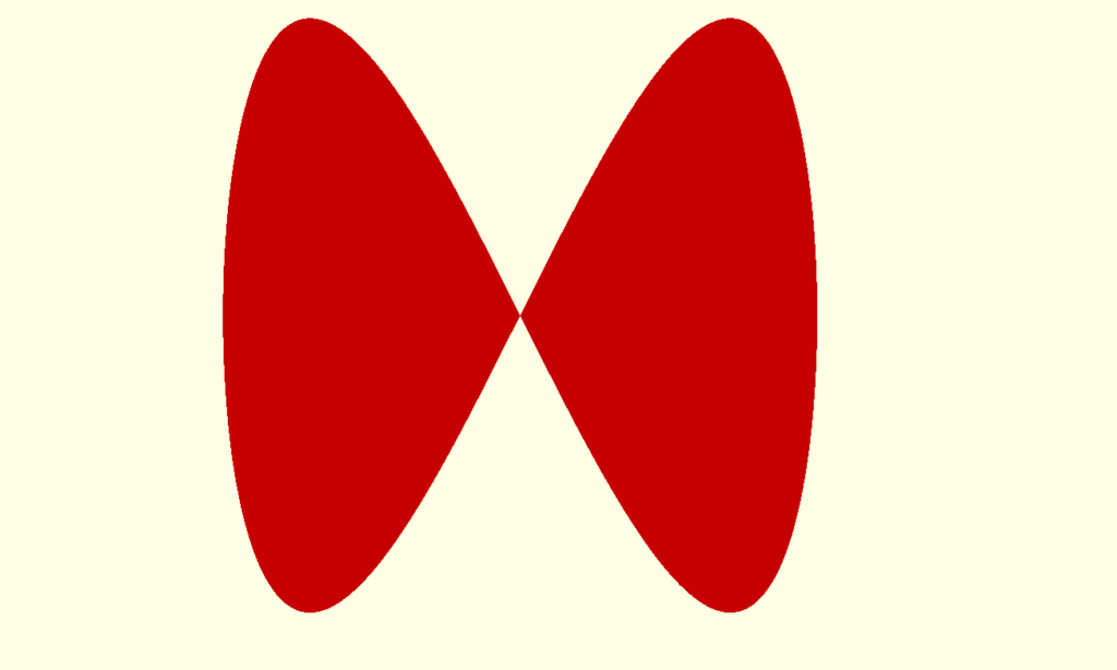
Now let’s take a look at the syntax of the function. Every function generates a value and in this case it is a list of points. In OpenSCAD a list of points in a two-dimensional space is represented by [[x1,y1],[x2,y2],[x3,y3],…] where all x’s and y’s are numbers. In this case of the circle function the point are generated in a for loop. The loop begin at 0 and ends at 720 with a step of 1. The radius * cos(phi/2) and radius * sin(phi) calculate each x,y coordinate for every given phi.
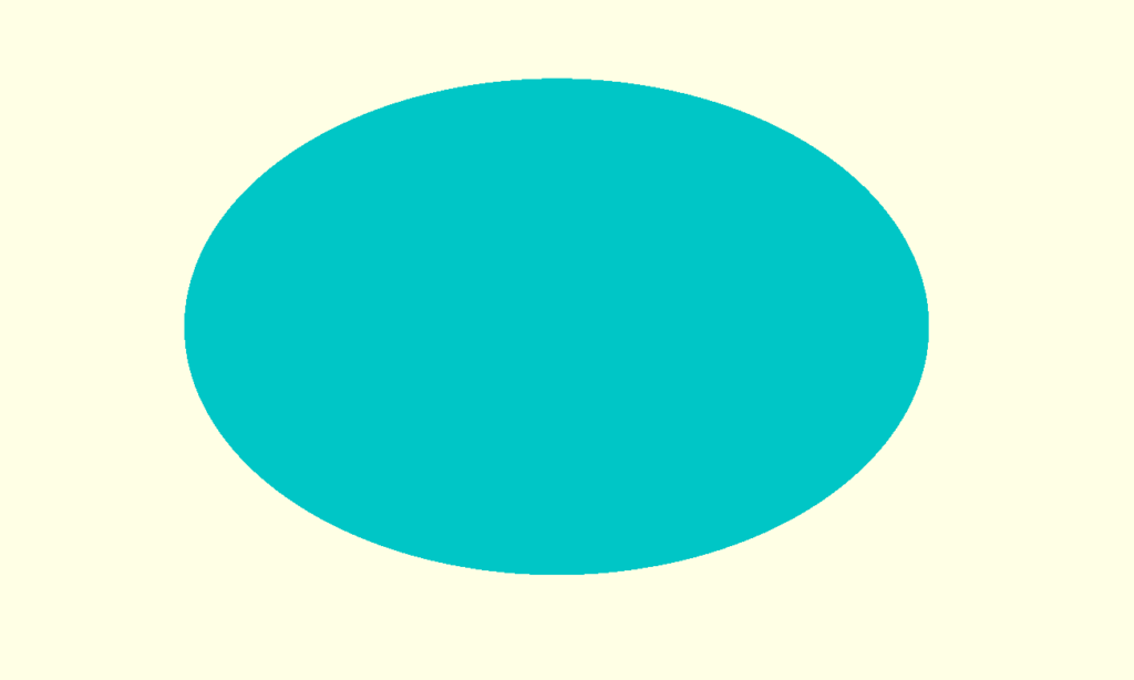
The ellipse, a generalization of the circle, can now easily be created by slightly changing our function.
function ellipse(r1, r2) = [for (theta = [0 : 1 : 360]) [r1 * cos(theta), r2 * sin(theta) ]];
color("cyan") polygon(ellipse(120,80));
a second parameter is added. r1 is the radius in the x-direction and r2 is the radius in the y-direction. If r1 is equal to r2 a circle is drawn.
Creating a 3D shape
To create a 3D shape is more complex than 2D. We use polyhedron function of OpenSCAD instead of polygon. For polyhedron to work we need a list of 3D points instead of 2D points and in addition a list of faces. Each face contains the indices of 3 or more point. All faces together should enclose the desired shape. So let’s start create a cylinder. First we need to calculate a list of the points of the cylinder.
h = 180; //height of the shape
step = 18; //height of one layer of the shape
a = 36; //step size for angle in degrees
r = 40; //radius of the base of the vase
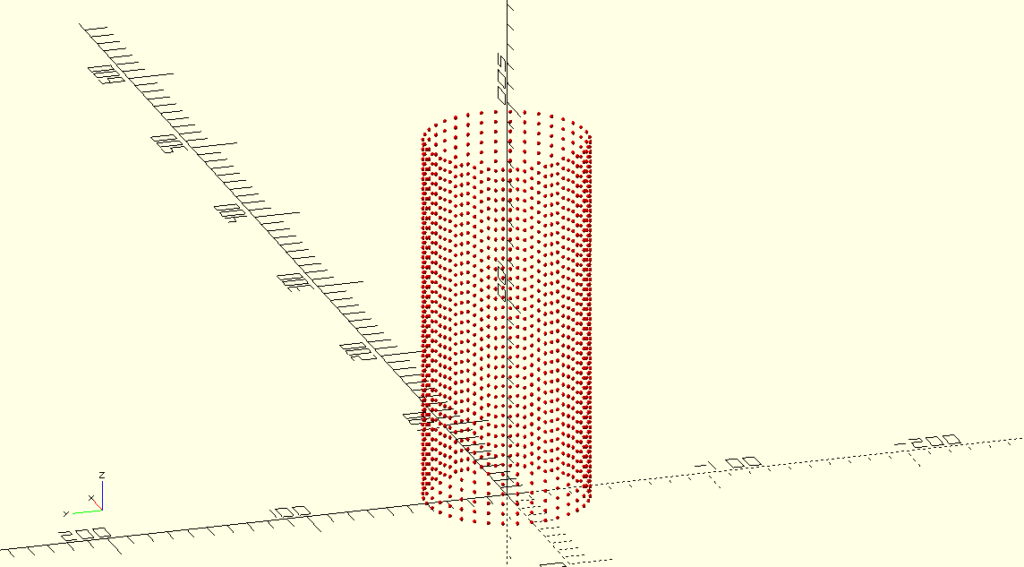
p = [for (z = [0:step:h], angle = [0:a:360-a]) [cos(angle) * r, sin(angle)* r,z]]; If you want to display these all the points in the list create the module plotList.
module plotList(p,c) {
    for (j = p) {
        color(c) translate(j) sphere(r=1.2,$fn=30);
    }
}
To display all the points in the list p in red type.
plotList(p,"red");Press F5 and a cloud of points in the shape of a cylinder will appear.
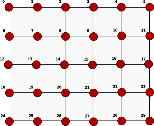
Next we need a list of faces. This is often the most difficult part. In this case we create faces that consists of four points.
Imagine that we define a matrix that has n columns and m rows and we use this to systematically work our way through the points to create perfectly connected rectangles. So the first rectangle will be [0,1,7,6], the second [1,2,8,7] etc.
If we want to translate the complete matrix above we need the code below. Note that instead of using fixed numbers for the matrix the size of the matrix is calculated based on the variables that we defined earlier.
m = floor(h/step); //number of rows in matrix
n = floor(360/a); //number of columns in matrix

fcs = [for (j = [1:m], i = [0:n-2]) [(n*(j-1))+i,(n*(j-1))+i+1,(n*j)+1+i,(n*j)+i]];
We are getting there but we also need to create a top and bottom separately or else we wouldn’t get a solid.
top = [for (i = [n*m:(n*m)+n-1]) i];

bottom = [for (i = [0:n-1]) i];
And we need to connect or stitch the end points by creating additional faces of each row of the matrix. For example [0,5,11,6] for the first row.
stitches = [for (j = [0:m-1]) [j*n,((j+1)*n)-1,(((j+2)*n)-1),(j+1)*n]];Next we need a list with all the faces that we created. We use the concat function for that.
fcsc = concat([bottom],fcs,stitches,[top]);Now with all the points and faces we can finally can the polyhedron function of OpenSCAD.
polyhedron(points=p, faces=fcsc);And this gets us the image below.
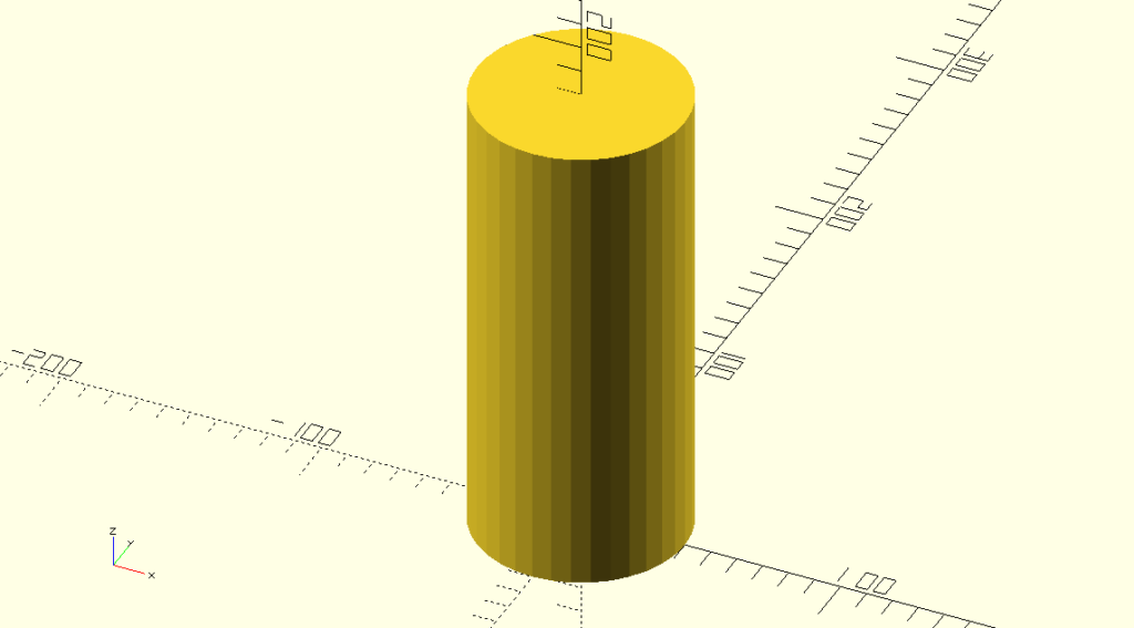
And our cylinder is complete. The complete OpenSCAD file (with an added twist) can be downloaded here: https://eroic42.nohost.me/nextcloud/s/wRwHSp6mtg3w96y
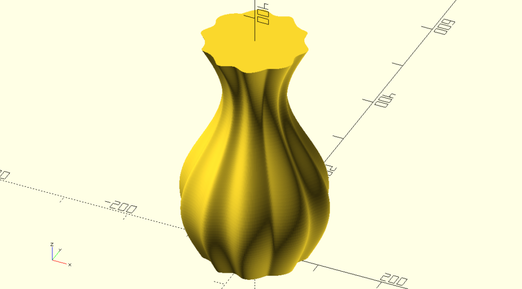
You could ask why choose such a complex method to create a cylinder. However just as with polygon this method enables us to create shapes that are impossible to do otherwise in OpenSCAD. Imagine to have the z-direction smoothly curved and on top of that have a periodic curve in the xy-plane of the shape. We would end up with a vase shown in the image below. It’s impossible to create this shape in another way in OpenSCAD. In a next post I’ll explain how to do that.
Conclusion
OpenSCAD allows the user to create complex 2D shapes using functions that generate lists of points This list is used as the argument in the polygon function of OpenSCAD. Every shape can be generated as long as the mathematical expressions are known and can be translated to OpenSCAD script. This opens up a world of possibilities. The same is true for 3D shapes but instead of polygon the more complex polyhedron function of OpenSCAD should be used.
Caveat: List comprehensions as shown in the functions of this article are only possible with OpenSCAD v2015.03 and above.
OpenSCAD is open source (GPLv2 license) and is well maintained by Marius Kintel et al. Besides the stable releases for Windows, OSX and Linux, development snapshots are available. I recommend using these development snapshots since they have all the latest features.
EDIT: If you render the cylinder that we created above, export it as an .stl file and import it in Prusaslicer you’ll see a message like “auto-repaired 2246 errors”. This problem is caused by the reversed normals on (part of) the faces. I’ll demonstrate how to solve this in a next post. The model however prints fine thanks to Prusaslicer.
The (somewhat older) video below demonstrates the 2D shapes. Click here to watch the video if the video below doesn’t play: https://peertube.linuxrocks.online/w/7NfsT6STabJ341ViP1eoMR
Thanks for reading!