In this post I’ll explain my reasons to leave YouTube. My videos will be available on PeerTube and new videos will be added there.
Categories
In this post I’ll explain my reasons to leave YouTube. My videos will be available on PeerTube and new videos will be added there.
I uploaded my sixth remastered Solvespace video to PeerTube.
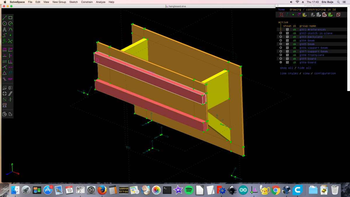
Solvespace is a good addition to the existing open source 3D CAD programs such as OpenSCAD and FreeCAD. If you want to try a truly free 3D CAD program but are intimidated by FreeCAD because of it’s steep learning curve and OpenSCAD because of programmers-like approach certainly should give Solvespace a try.
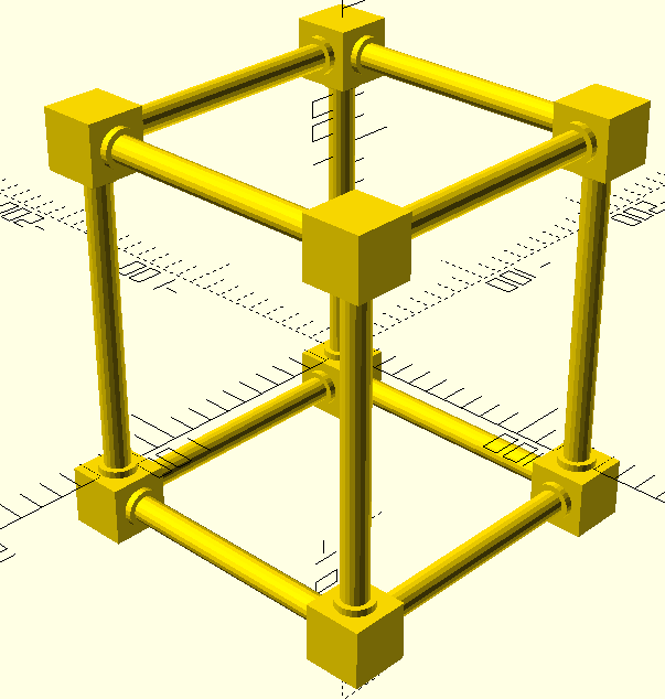
DIY frame for a Photography Light Box. I designed a 3d printed three way connector to assemble the curtain rods for the box.
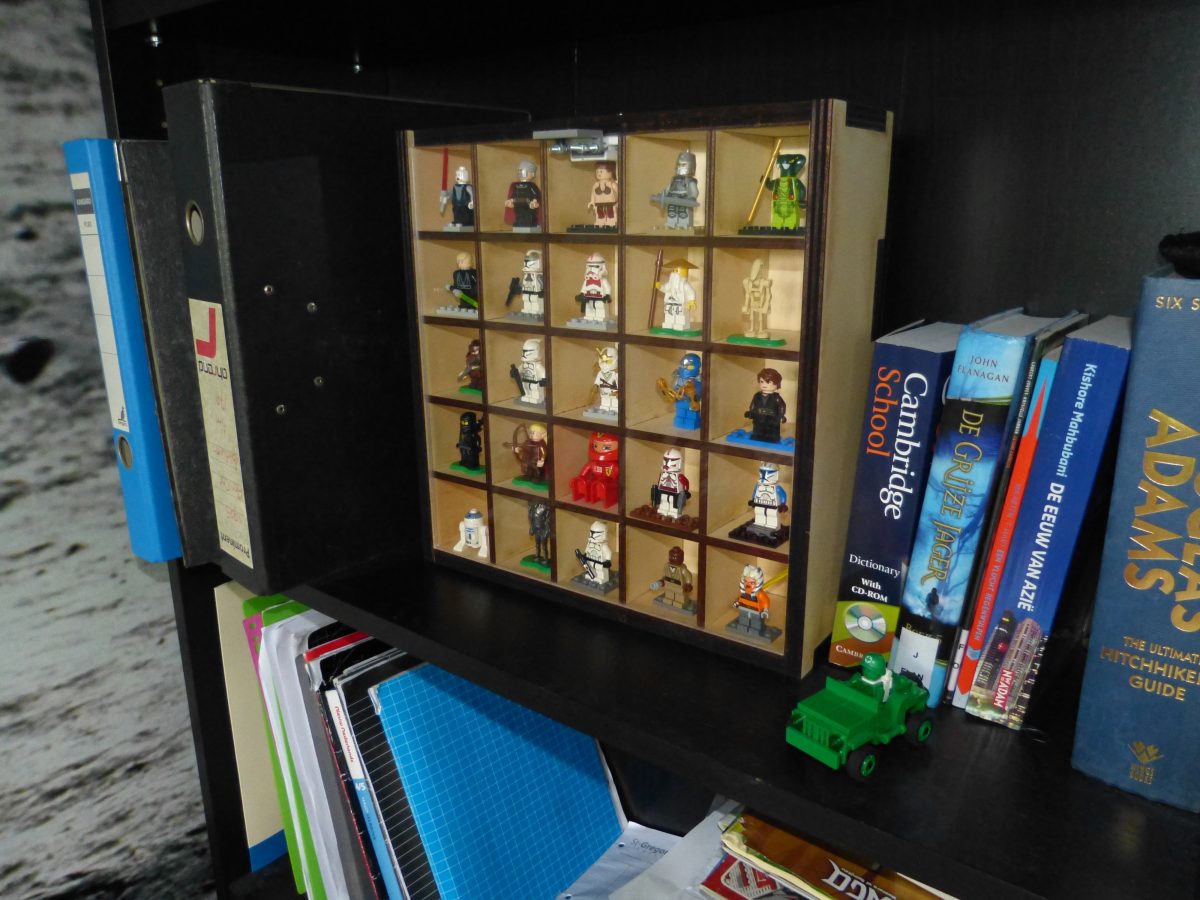
Making a woorden Lego cabinet for all this minifigs is easy and cheap. You do need a laser cutter for this project.
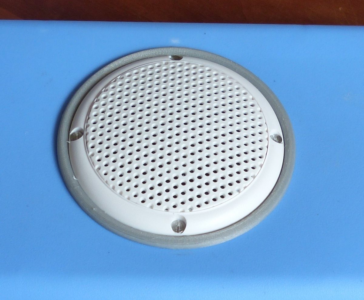
Filaflex is excellent material to improve the audio cooler that I made earlier. The material is very flexible and surprisingly strong making it perfect for sealing purposes
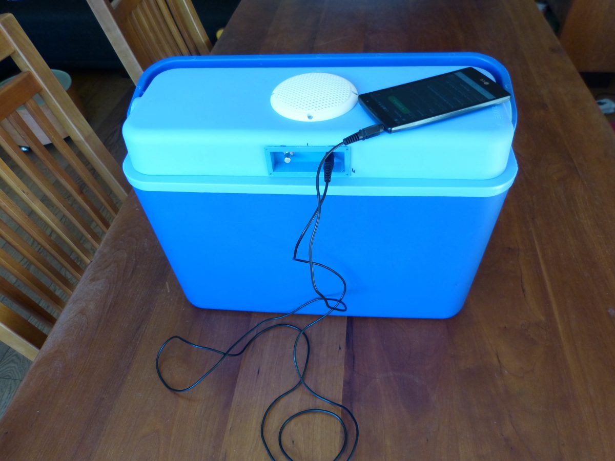
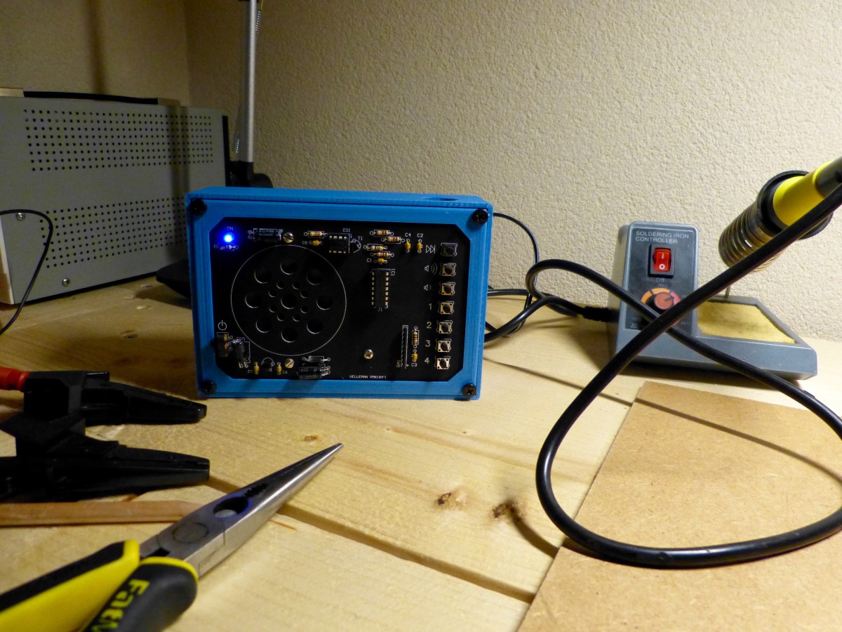
A made a 3d printed enclosure for the audio components that fits in the coolers lid together with a simple console to operate the audio
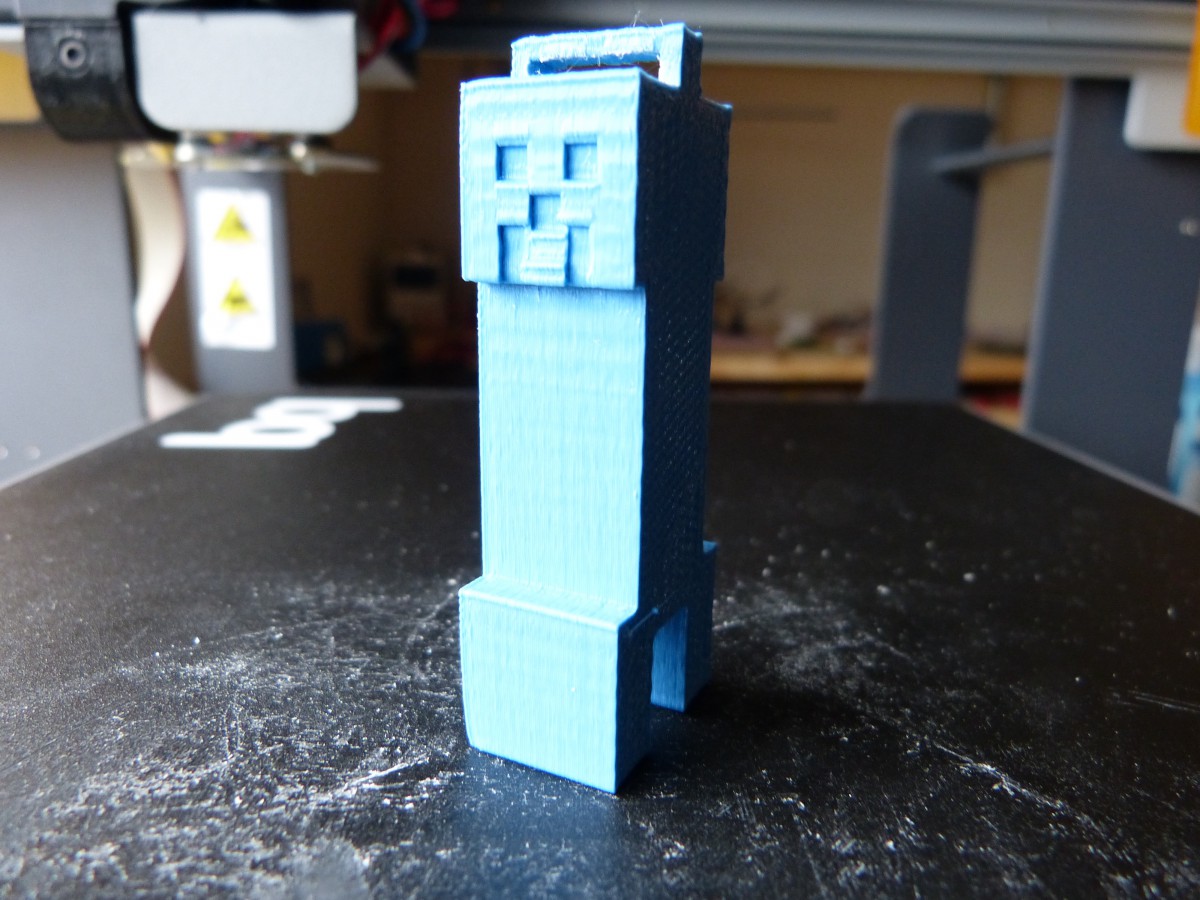
putting my 3D printer to use
Making good use of a 3d printer
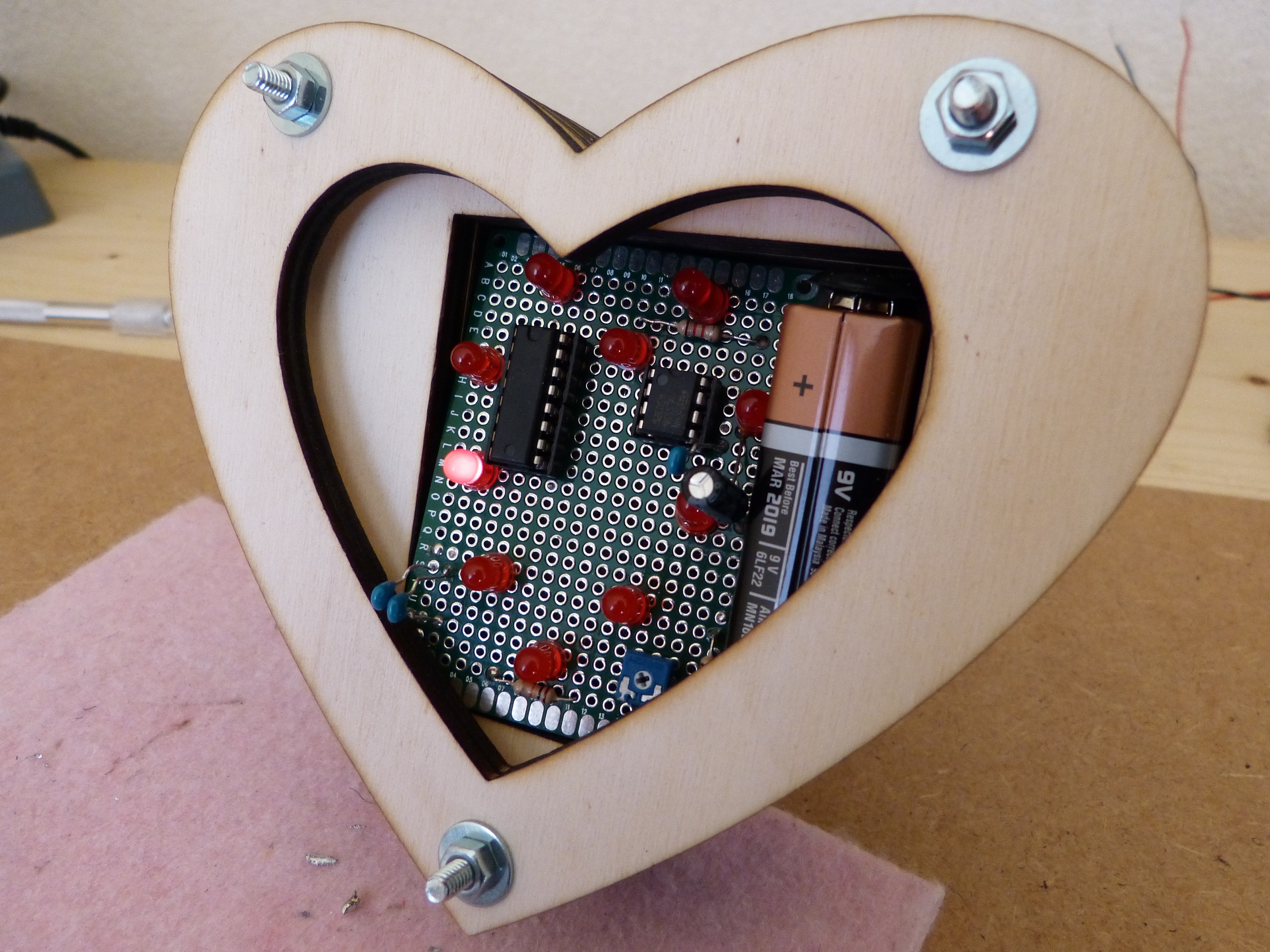
Looking for an idea for Valentine’s day. Look no further.