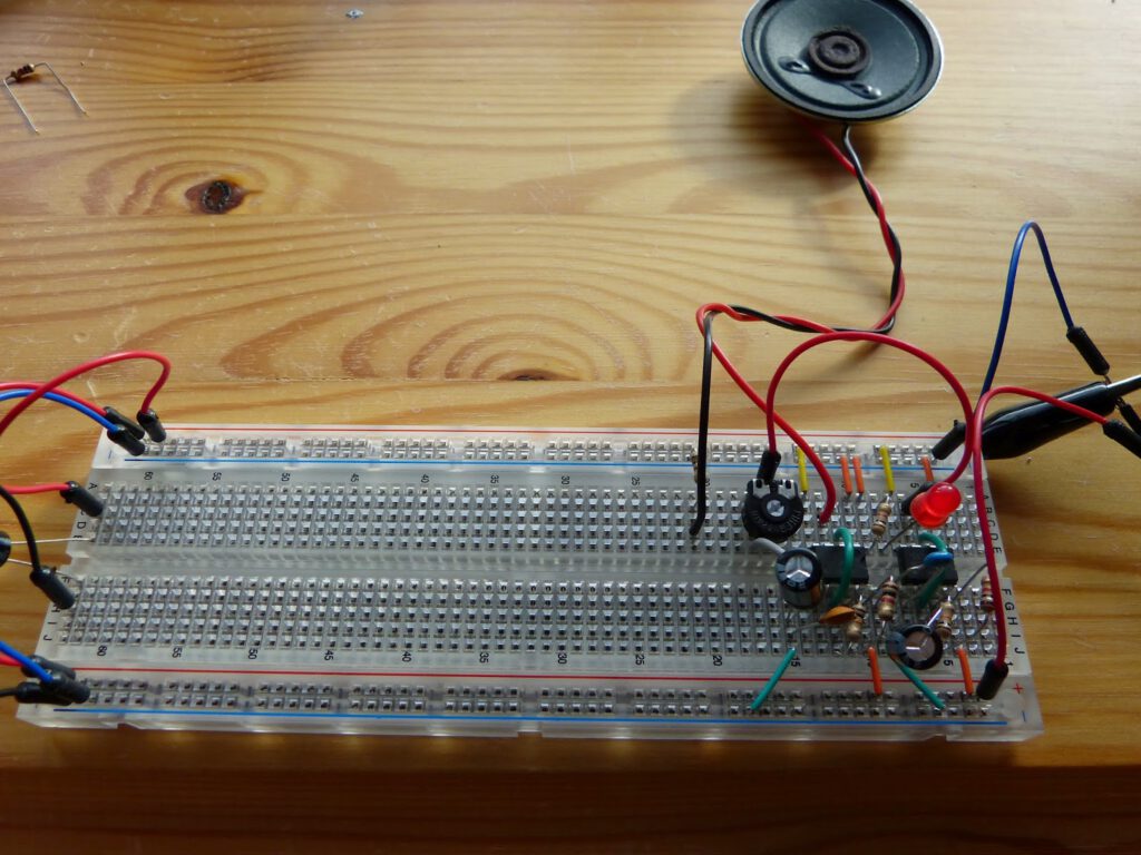
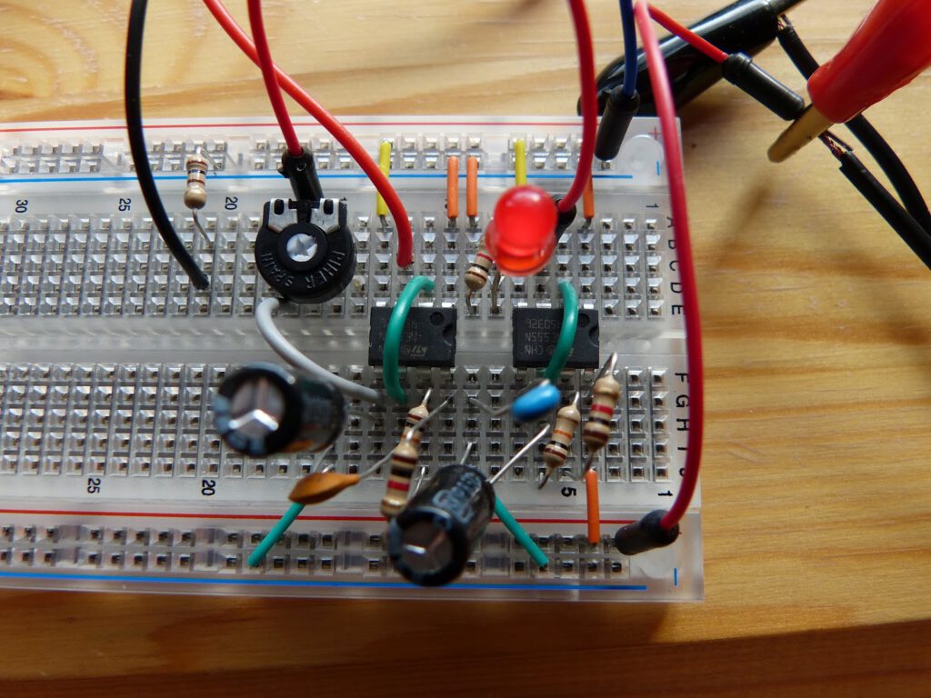
While working on the Atari Punk Console I reread the part of chaining chips in Experiment 17 of Make:Electronics (pg167). I then realized that I didn’t do all the experiments that are described in the book. Since Experiment 17 contains a lot of information and chaining 555 chips is common practice in electronics I decided to at least one of the remaining experiments. This experiment is described in figure 4-30 (pg169). In this experiment the output of the first 555 chip is connected to the control (pin 5) of the second 555 chip. Both timers are in astable mode. The second chip drives a speaker. The first 555 chip, that oscillates slowly, slowly decreasing the pitch of the of the sound generated by the second chip until the cycle of the first chip ends and the frequency drops. This results in a slow whoop like the sound of a siren.
After building the circuit the sound produced was very distorted and unlike the slow whoop I was expecting. The LED connected to the first chip performed as expected with about one pulse per second. After inspection of the circuit I noticed that the 100 ohms resistor in series with the speaker had become very hot. I changed it for a resistor of 180 ohms and now the circuit worked fine. I substituted a 10K potentiometer (see images below) for the R7 resistor (1K) which made some interesting changes in the slow whoop (higher or lower pitched).
At this point in the book I believe the use of an oscilloscope would become interesting even helpful. I would be able to analyze the waveform on several pins of the circuit. The oscilloscope is however an expensive piece of equipment which I don’t own yet. It will put it on my wish list. Something I noticed with this hobby that there appears to be an ever increasing need for space, equipment and components.
I’ve added a video of the experiment, with several tweaks of the circuit,you can watch it at the bottom of this page.

