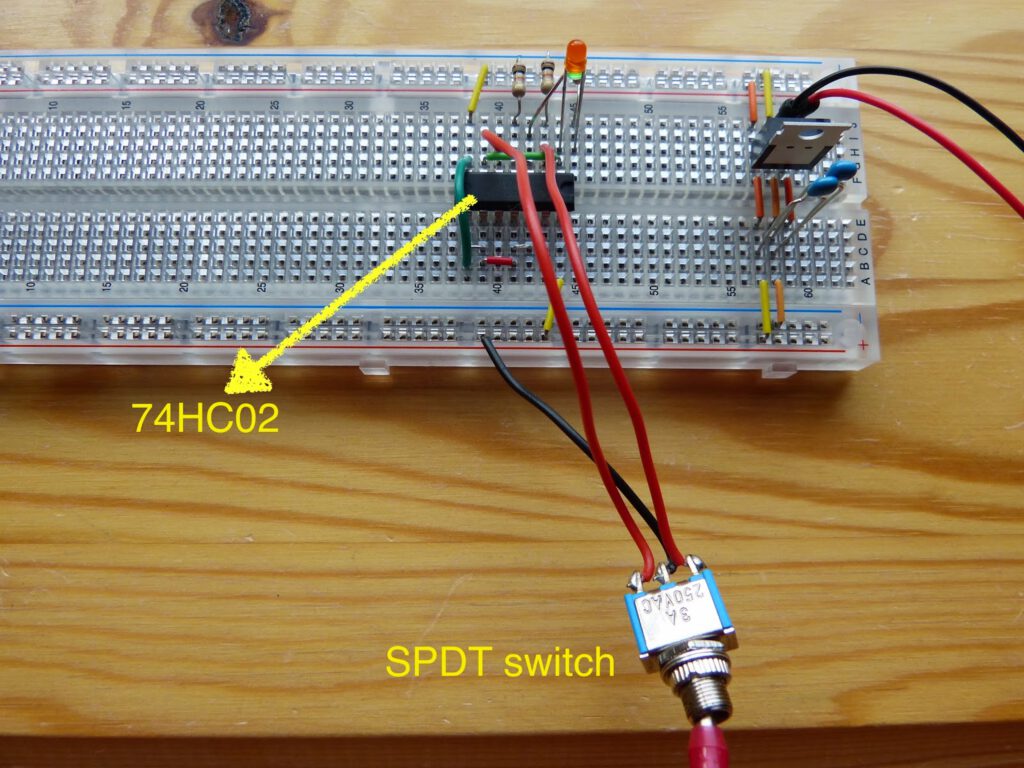
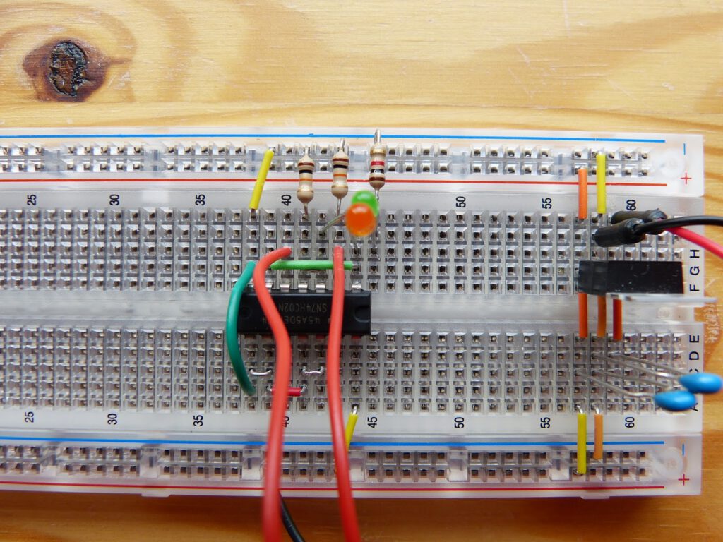
Experiment 22 of the book Make: Electronics is a simple experiment to demonstrate use the 74HC02 logic chip as a flip-flop. The 74HC02 is a logic chip with four NOR gates. The schematic of this experiment can be found in figure 4-98 on page 21 of the book. A SPDT switch is used to flip the circuit in one of the two possible states. The state is indicated by two LED’s connected to two different NOR gates. Other input, in this case pulling a wire from the switch out of the breadboard, is ignored by the circuit (debounce).
Building this circuit is simple by now. I already soldered wires to the SPDT switch for the previous experiment. When the circuit is powered one of the LED’s lights up. Flipping the switch lights the other LED. When I turn the switch a positive current is send to the a NOR gate. The negative current of this NOR gate crosses over to the input of the other NOR gate creating a positive output on this gate. The circuit can be rewired with NAND gates (74HC00 logic chip) and negative switched input.
A video of this experiment can be found on my PeerTube channel at https://peertube.linuxrocks.online/w/8Aw9X5qgKU1EzZhX9duEh6.
Thanks for reading!