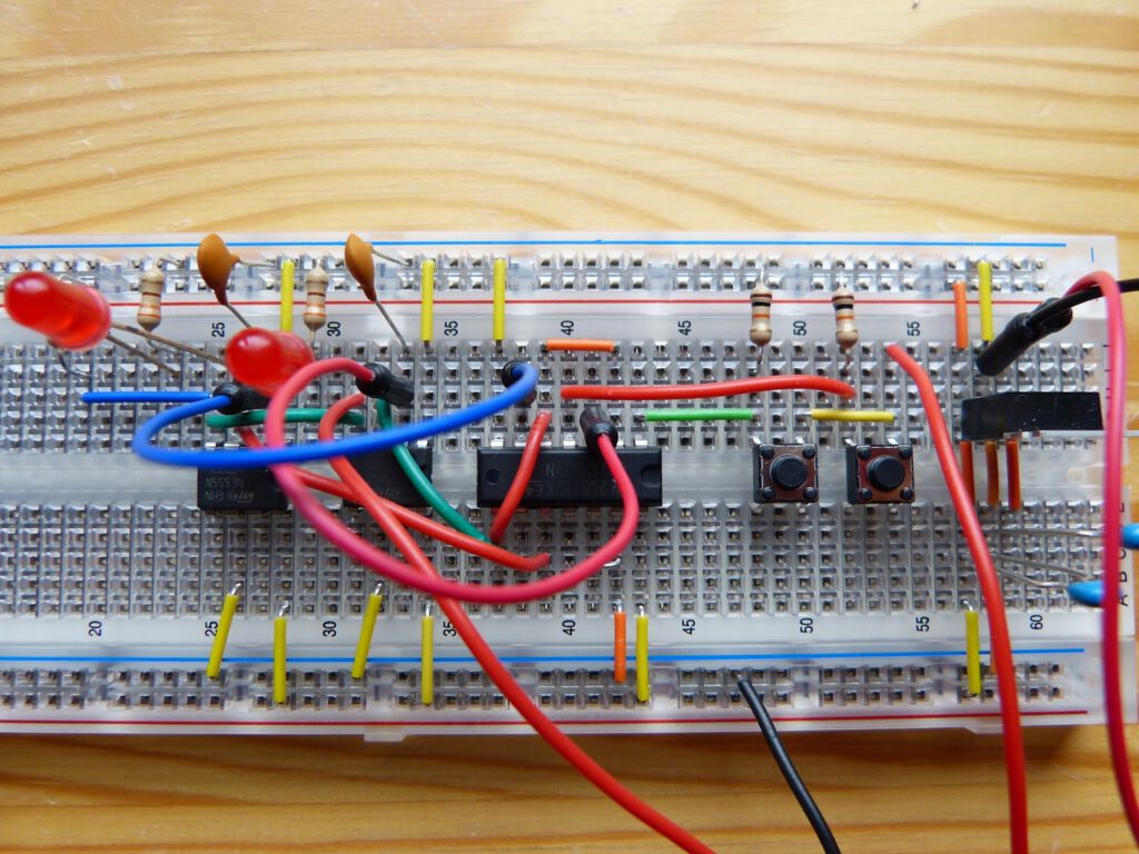
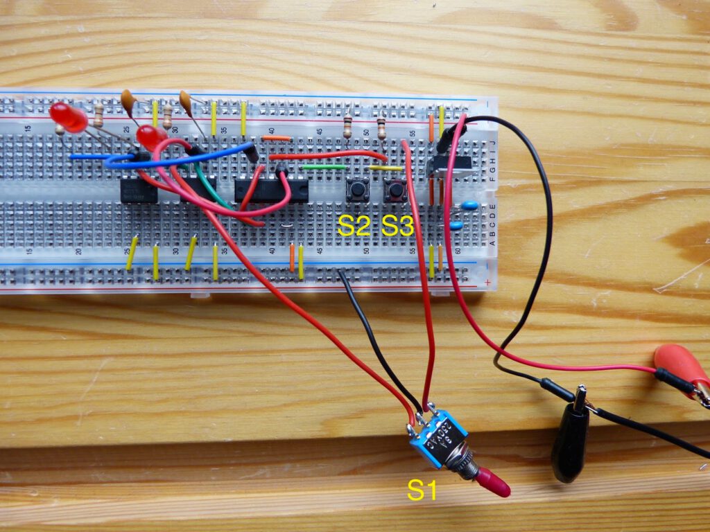
Experiment 21: Race to Place from Make: Electronics describes a circuit useful for a quiz show like Jeopardy. Pushing a button lights an LED and locks the button of the other player(s). The two player schematic is depicted in figure 4-95 on page 208 of the book and is built around the 74HC32 logic chip (with four OR gates) and two 555 timer chip in bistable mode. The circuit can easily be extended to three players (figure 4-94). Pushing a button (e.g. S2) triggers pin 2 of the first 555 timer. The output from this timer locks pin 2 from the other timer by keeping the voltage high.
Compared to the previous experiment this circuit is relatively easy to build on the breadboard. Nevertheless, I made a mistake. I forgot to connect the output of the second OR gate of the 74HC32 chip to the second 555 timer. As a consequence pushing S3 didn’t light up the second LED and the other button was not locked. After comparing the circuit on the breadboard with the schematic I discovered my mistake and corrected it.
I uploaded a video on this experiment to my YouTube channel at https://peertube.linuxrocks.online/w/jphRFooeVTsJr9ZVRGYr2Z
Thanks for reading!