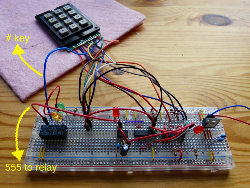
After having done most of the circuitry of Experiment 20 yesterday today I connected the relay and all loose wires from the keypad to the circuit. I had to read the description of some of the experiments with relays earlier in the book Make: Electronics (e.g. experiment 7) again to be able to wire the relay correctly. I added a yellow LED indicating that the relay is flipped in the off state and a green LED relay indicating that the relay is flipped to the on state (see image below).
The circuit now functions as follows. When the asterix is pressed the LED on the right side of the circuit is lit. While this key is pressed the code 1-4-7 is pressed. Next the LED just above the 555 is lit for a brief moment. Then the relay flips on and the green LED lights up. To flip it off again I have to press the hashtag on the keypad, the relay flips off and the yellow LED lights up.
I noticed on YouTube (https://www.youtube.com/watch?v=owvgzOeLOo0 at 2:30) that another reader of the book needed a 2N2222 transistor to amplify to signal from the 555 timer. I had no such problem.
I made a short video of this experiment. You can find it on YouTube at: https://peertube.linuxrocks.online/w/wLfBsDJ4ou1RDorrVWadMA
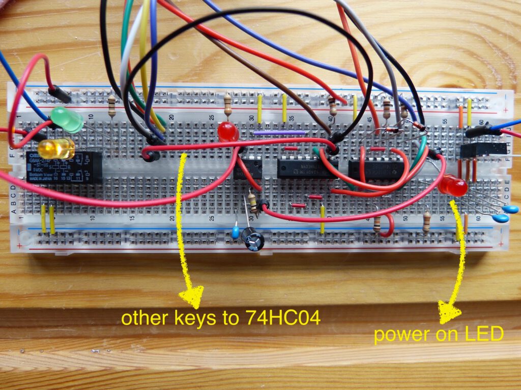
The yellow arrow on the left indicates all other wires from the keypad (0,2,3,5,6,8,9) to the first inverter on the 74HC04. The other yellow arrow indicates the LED that is lit after the asterix is pressed on the keypad.
Thanks for reading!