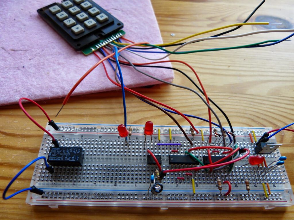
Experiment 20 of Make:Electronics describes a hardware device that protects a computer (or any other electrical device) from being used unless a specific numeric code is entered on a keypad. The experiment is built around two 7400 logic chips (74HC08 and 74HC04). These chips process the input from the keyboard and trigger a 555 chip if the three digit input is correct. The 555 chip in turn switches a (latching) relay.
Initially I had a problem finding a numeric keypad suitable for this experiment. The Velleman 12 keys Keypad KP-12 wasn’t available at my local supplier. Luckily I found an alternative that is fulfilled the requirements (and looks suspiciously similar to the Velleman).
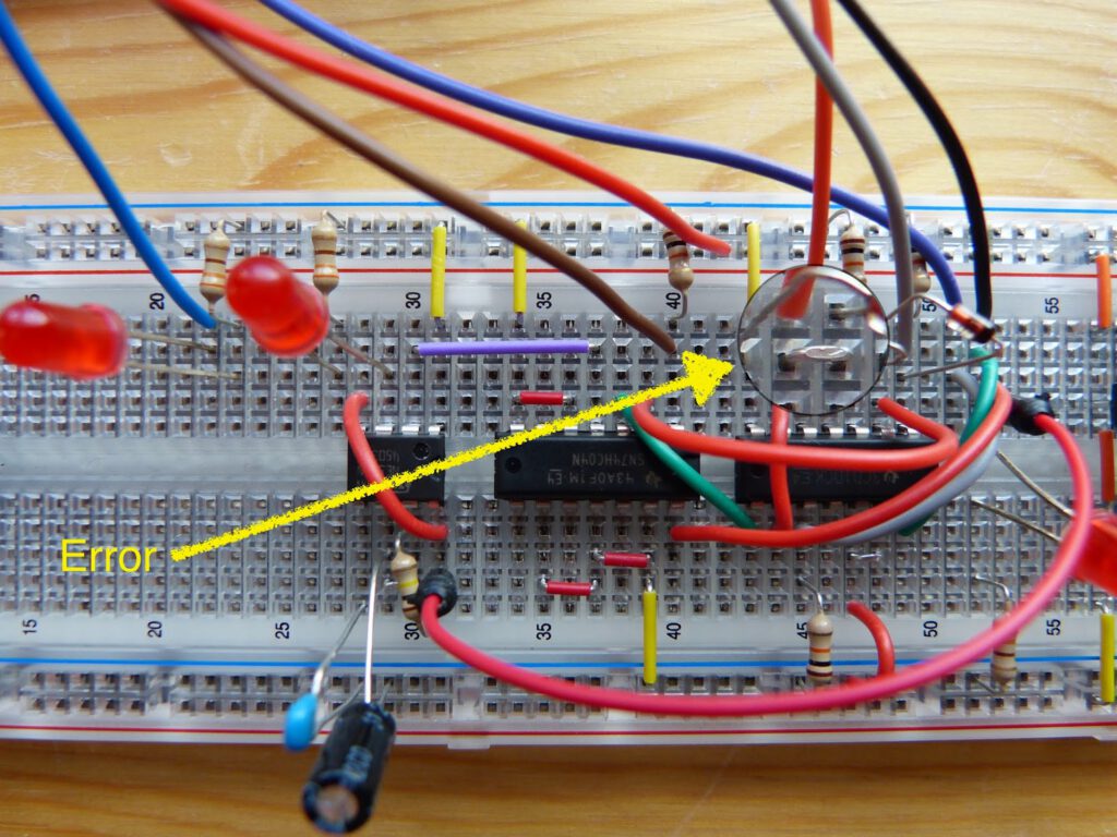
Breadboarding was done according to figure 4-84 of the book. I double checked all the connections. At this stage I left the relay out and tested the circuit. After punching 1-4-7 the LED on the output the 555 timer lit up however with further testing I discovered a problem. Every numeral code that includes 1 and then 7 lit up the LED (e.g. 1-9-7). After comparing the circuit on my breadboard with figure 4-84 I discovered that I mistakenly had pin 4 and pin 5 of the 74HC08 logic chip connected (see image below). Also digit 4 of the keypad was connected to pin 5 instead of 4. After I corrected the mistakes everything worked fine. Next I’ll try to connect the relay to the circuit.
Thanks for reading!