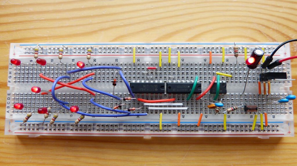
In this part of experiment 23 of Make: Electronics the binary counter from part 1 is upgraded to a dice simulator (figure 4-109 on page 219). A 74LS27 chip is added. This chip has three NOR gates of which one is used for this experiment. Also an LED display is added. The configuration of this display represents a die. The speed of the 555 chip is changed from 1 to 50.000 pulses per second. When the push button is released the new 68uF capacitor discharges over the 555 chip and the frequency of this timer will slowly decrease and eventually forcing the LED display to stop at a number between one and six.
For this experiment you need to take extra care because of the complexity. First I made a mistake with the addition of the (68uF) capacitor and the push button. I had placed the push button in one vertical row on the breadboard and effectively shorting it (I know that’s stupid). Luckily I noticed that the LM7805 voltage regulator was becoming very hot. Furthermore it also took me some time to figure out a good configuration of the LED display. After this I encountered no further problems. I tested the circuit and found out that it appears to be randomly ‘throwing the die’. After 30 ‘throws’ all numbers from one to six appeared exactly five times.
I do not have the 74LS06 chip that is needed for the enhancements paragraph (page 220) of this experiment so I will skip that.
I uploaded a video of this experiment on YouTube at https://www.youtube.com/watch?v=yRpUvRb6SMM.

Thanks for reading!