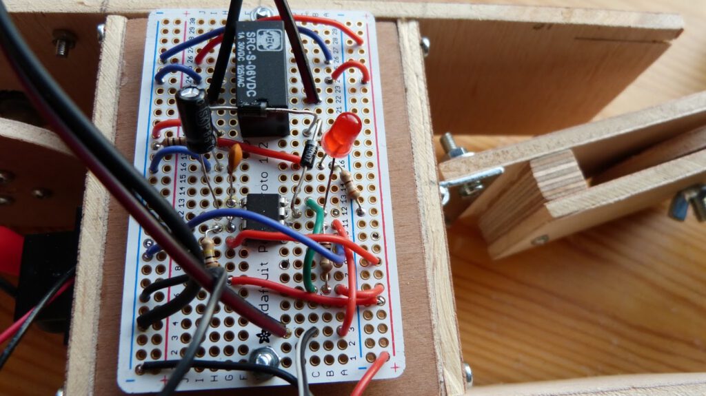
In my previous post about the robot cart I described how I finished the cart and tested the circuit on the breadboard. I only had to solder the circuit to the perf board and mount the board on the cart. Simple, right. Unfortunately it wasn’t that simple. After soldering I tested the board and discovered that there was a problem. The motor would spin and when I pushed the button it would reverse as intended however it never reverted to the original direction. I replaced several components such as the 555 chip but that didn’t help. When measuring the voltage on the pins of the 555 chip I found that it worked exactly as intended. I was mystified and beginning to feel desperate but then I recalled that there was an errata page on the book Make:Electronics. On this page I found someone describing the same problem that I had. Charles Platt the author of the book acknowledges the problem and possible solutions are offered. Searching on the internet for 555 timer relay I found a comparable schematic on cdelectronics.com. It basically adds two diodes to the schematic of the book (figure 5-98). One diode from the output of the 555 timer to the relay (to energise the coil) and a second across the coil.
I added the two diodes to my board and tested it. I found that it works on 6V DC but barely. Due to the voltage drop on the first diode just 3.8V remains over the coil, just enough to energise it (for this specific relay: SRC-S-06VDC). If the battery voltage drops below 6V the coil is no longer energised. I therefore decided to use 9V DC block battery instead of 6V. This should provide a wide margin for operation without damaging the relay.
NOTE: I found that other people were having good results with just a diode across the coil. Here is a link to such an example. That didn’t work for me possibly to due the relay that I use.
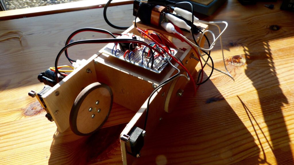
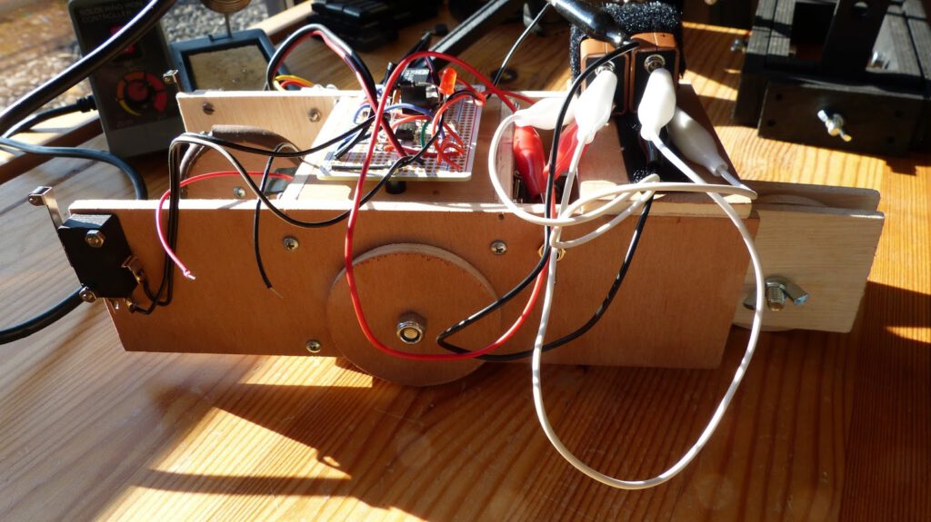
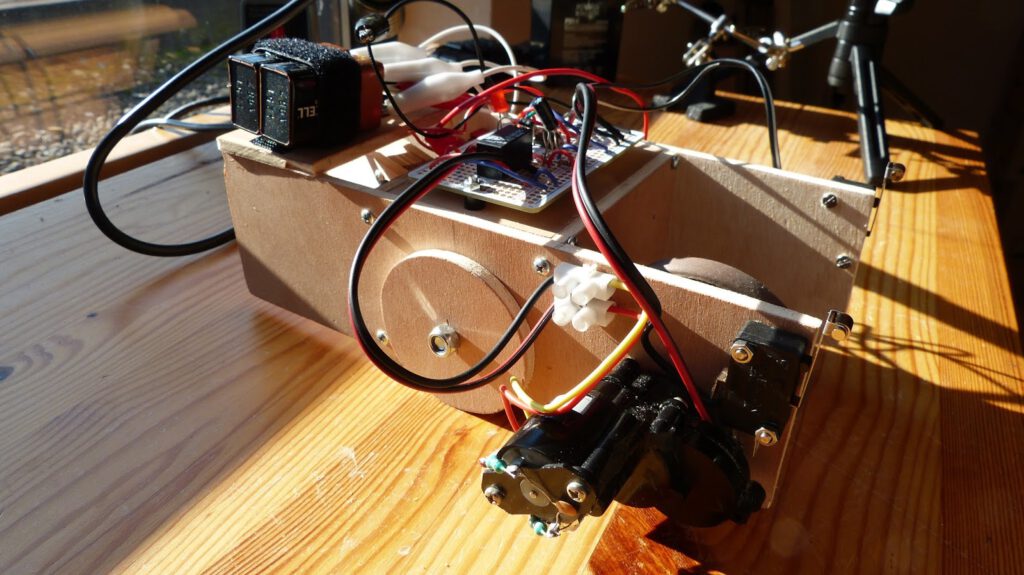
Next I’ll mounted the perf board (I used the handy half-size perma protoboard from Adafruit for this which I picked up for 4.95 euro) and the battery on the cart. I connected the the motor, battery and switches to the perf board. Then it was time to test the cart. The first test went miserably because the cart didn’t react to the switches. I then connected my bench power supply to the cart and it worked fine. I figured that the capacity of one block battery is insufficient to power the cart. I solved this by placing two block batteries in parallel which doubles the capacity of the power source.
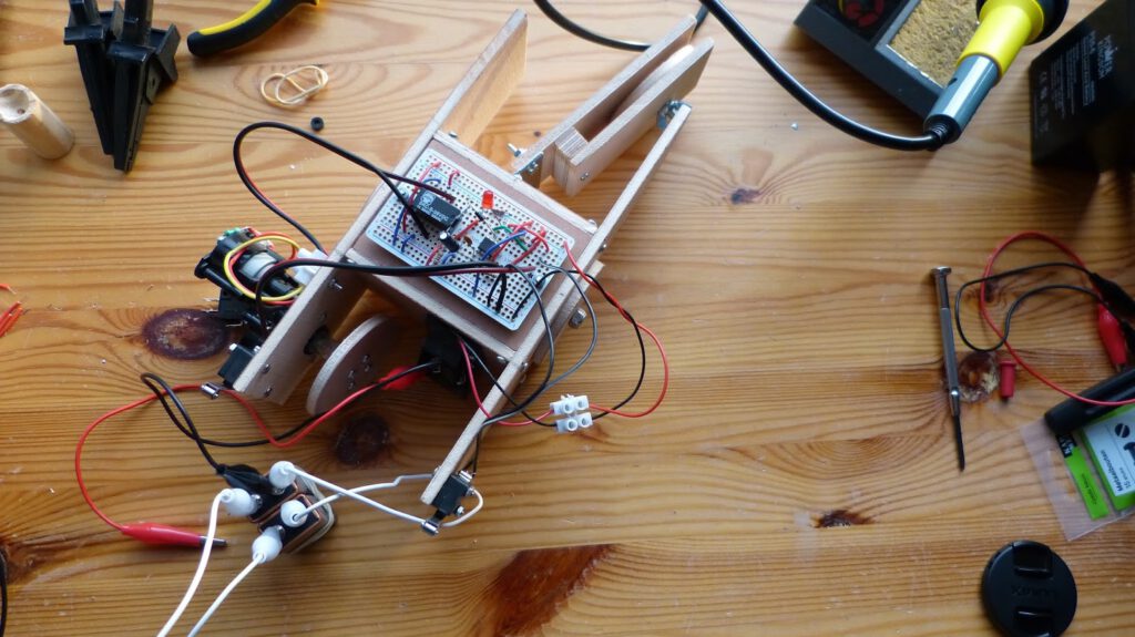
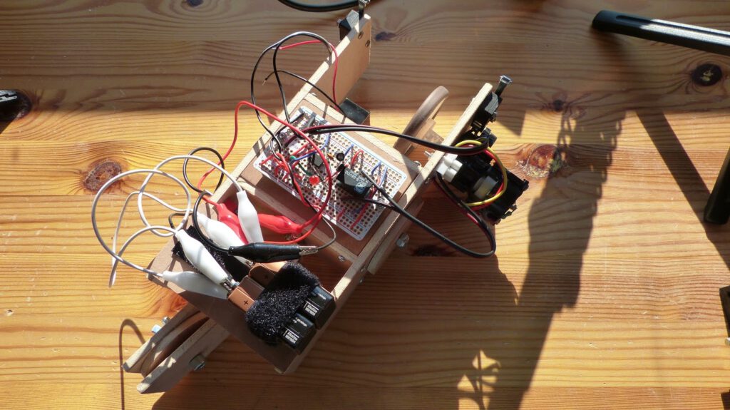
With the power problem solved I made the last additions to the cart. I added an on/off switch and a glued a piece of plywood with velcro on it to the back of the cart. I attached the two block batteries to the velcro. Lastly I glued rubber to the front wheel to get more grip.
While testing the cart I noted that it runs way to fast. I already damaged a sensor when cart hit a closet. Also the alligator clips come loose when the cart hits something. Nevertheless I feel I have nearly completed this experiment. I’ll probably replace the motor for one with lower RPM (and a less power hungry one).
Thanks for reading!