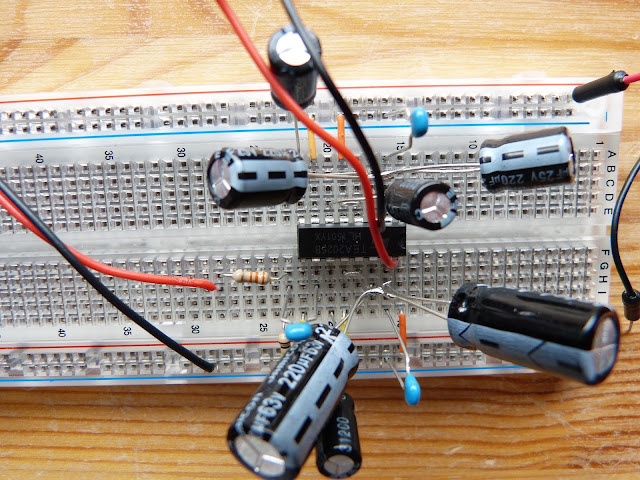
This experiment of Make: Electronics demonstrates the use of self-inductance and capacitance in audio filtering. The low and high frequencies of the audio signal can be separated and send to different speakers (woofer and tweeter). The audio chip used for this experiment is the TEA2025B, a somewhat older chip that was used in portable radio cassette players (remember the Sony Walkman). For this experiment I needed a 5-inch speaker. I was able to find an old woofer that came from an sound system that’s no longer in use. This particular woofer is 4 inch , 6 ohm (according to the book a minimum 5-inch and 8 ohm speaker is required) and maximum of 40W. I made the two nonpolarized capacitors out of two 220uF capacitors as indicated in figure 5-38 of the book (pg. 249). The experiment requires two .15uF electrolytic capacitors which I do not have. I use two 100nF ceramic capacitors instead.
I have build the circuit temporarily without filtering for two reasons. The first reason is that I want to use this circuit to test the TEA2025B’s that I bought from Aliexpress which were in a very bad shape when they arrived. Secondly I want to rule out problems in the non-filtering part of the circuit.
 |
| Overview of the experiment. With on the left side the 4-inch speaker. The audio is supplied by a Nexus 7 inch tablet. |
My first try didn’t go so well. After powering up the circuit the first half minute or so the sound is sort of ok but than a terrible distortion kicks in and makes listening unbearable. Furthermore the TEA2025B becomes extremely hot. I unplugged and checked for errors but couldn’t find none. I figured that I’m overdriving the amplifier so I increased the 33K and 10K resistor to 100K and 33K respectively without result. I then changed the TEA2025B for another one, again no result. Finally I decreased the voltage to 4,5V (instead of 9V). Now the distortion is gone but I’m still not happy with the sound quality. The sound is very muffled and undefined (sorry I don’t have any words to describe it). Not sure how to go forward from here.
 |
| Close-up of the breadboard. The oddly shaped capacitors are the non-polarized capacitors that I made from 220uF capacitors. |
Thanks for reading!