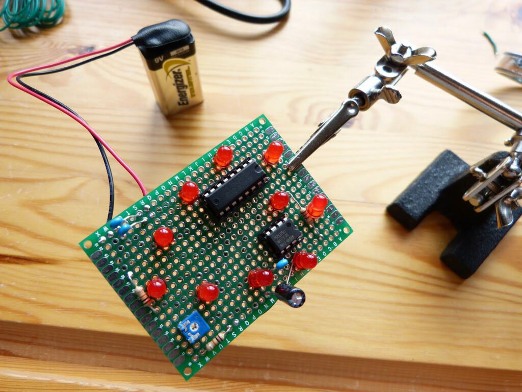
I reread the part of Make:Electronics about the inside of the 555 timer in the astable mode (page 162 of the book) hoping that this would give me a clue about what went wrong with the Valentine LED chaser. This gave me the idea that the 1 uF capacitor connected to the pin 6 of the 555 timer wasn’t properly charging or discharging. After examining the circuit board I understood why. I had soldered the 10K resistor protecting the potentiometer to the wrong side of the capacitor, the negative side. Therefore the capacitor simply didn’t charge. I disconnected the resistor from the negative side of the capacitor and re-soldered it to the positive side. Everything worked fine now. I’m glad the circuit works however the lay-out of the circuit could have been simpler to avoid the spaghetti of wires that I ended up with. All in all a nice deviation from the book. With everything I learned this far from Make:Electronics I was able to finish the Valentine LED chaser (Remember that I had hardly any electronic skills when I started with the book). A short video of this project can be found on below.