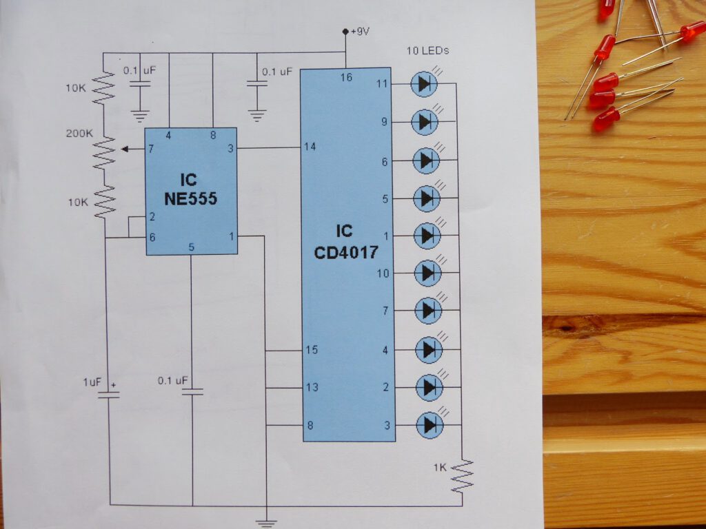
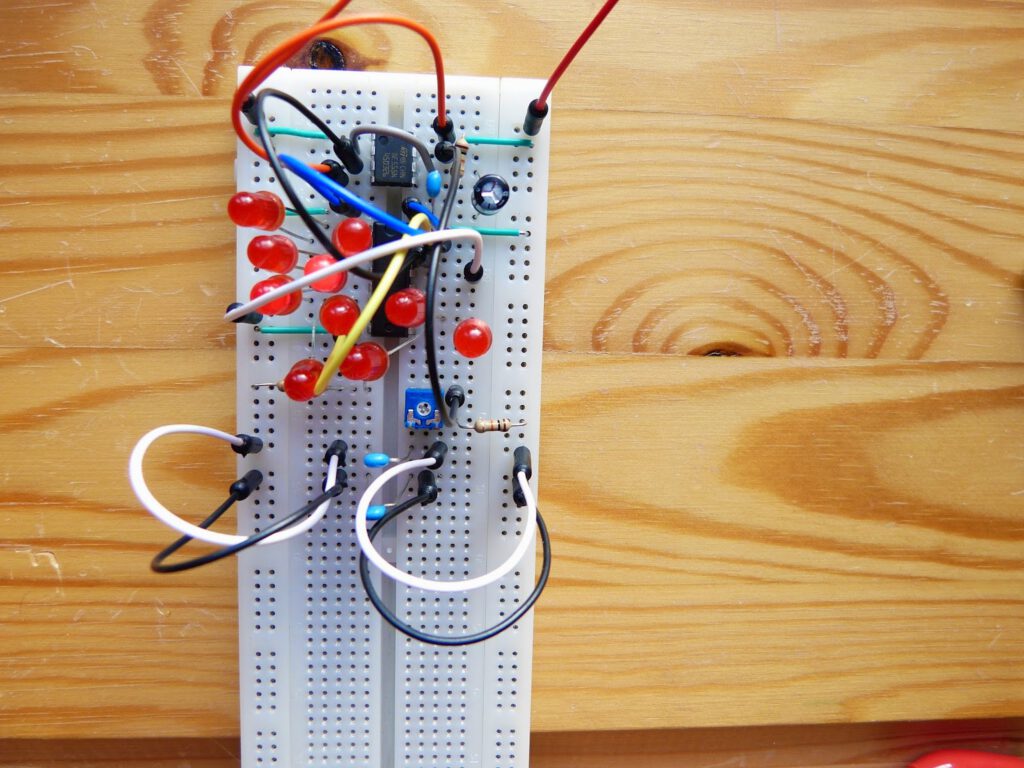
It is time to take a temporary departure from Make:Electronics. The question is: has all these theory and experiments from the book enabled me to finish my own project? After working with the 555 timer in astable mode last week I remembered an article about this chip that I read a year ago, the so called LED chaser. I read the article last year on the Makezine website. It’s an electronic circuit that illuminates ten LED’s in the shape of a heart (you can find the article here). With Valentine day next Saturday this could be a nice present for my wife. The circuit needs a 555 timer, a 4017B decade counter, some capacitors and resistors, a potentiometer and of course 10 red LED’s. Luckily I had all the components (I used 1.2K resistor instead of 1K and 250K potentiometer instead of 200K). I have built the circuit on a breadboard today and it worked almost immediately. That leaves me almost a week to solder it to a board. Take me to part 2.