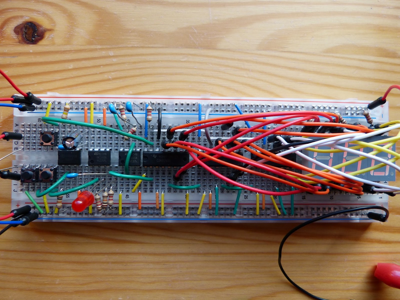
I (almost) finished the reaction timer today. That means that the delay is build in. This was done by adding yet another 555 timer now in monostable mode. It is triggered with a tactile switch connected to pin 2 of the timer (see pg. 178 of Make:Electronics). During testing of the circuit the LED switched on immediately which was not supposed to happen. After some investigation I discovered that the resistor connected to pin 7 of the last added 555 chip was 330 ohm instead of 330k allowing the capacitor (C5) to be charged far to quick. After solving the problem I exchanged the capacitor of the first 555 chip (C2 in astable mode) from 100uF to 0.1uF increasing the number of pulses per second a thousand fold. Finally I was able to test my reaction. In conclusion Experiment 18 is by far the most complex circuit that I plugged into a breadboard. Nevertheless due to the step-by-step of the book approach I was able to complete without too much trouble. Linking IC’s together is demonstrated very well with this experiment.
Further text at page 179 and 180 suggests how to calibrate the whole circuit without an oscilloscope. At this point I’m not sure if I want to do this because I don’t want to take this project any further by enhancing it or even create a project box.
The video of the different stages of experiment 18: