With the arrival of the Kingbright numeric LED with the correct width (see my earlier post) I was able to continue experiment 18 of the book Make:Electronics (pg. 170). In this experiment the reader will eventually build a reaction timer using the 555 timer chip and 4026 decade counter. The layout of my numeric LED is a little different than the one from the book so I have to change the connections to the 4026 decade counter later in the experiment accordingly.
In the first part of this experiment you simply test display. This is done by sticking the three numeric LED’s in the breadboard and applying voltage to the succesive pins. Before applying the voltage I connected pin three of every LED to the negative site with a resistor in between. Then I connected positive voltage to all the other pins (see image below).
Next I connected a 4026 chip to one numeric LED. Connecting is easy. The only problem is that I needed a lot of connections already while later in this experiment all three LED will be connected. Pressing the tactile switch sometimes prompted the display to skip a number. This effect is described as switch bounce and described on pg. 174 of the book. Apart from that the whole experiment went pretty smooth (see the video below). To be continued.
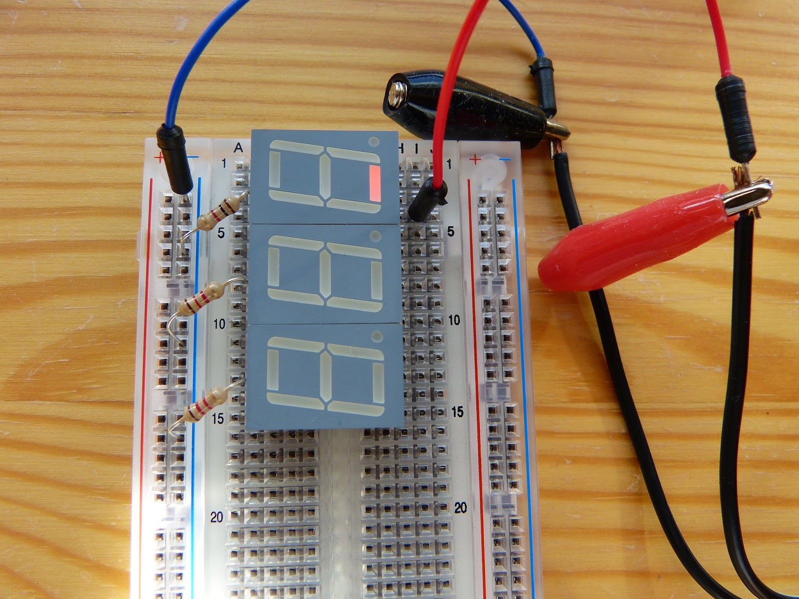 |
| Applying positive voltage to a pin of the first numeric LED. |
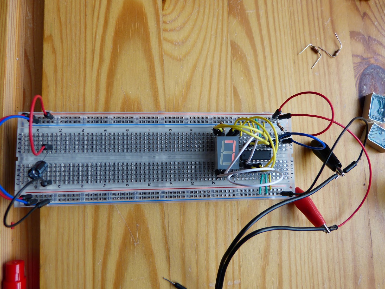 |
| Numeric LED connected to the 4026 decade counter. |