Introduction
Last June I wrote about a Darth Vader voice changer that I made. Back then I used the Velleman MK171 kit as the electronic part of the voice changer. Although it worked pretty well I felt that some area’s needed improvement. First, I couldn’t get the push buttons mounted on the housing to work making it hard to switch the voice effect. Second, I didn’t like the limitations that obviously come with such a kit; you’re more or less bound to the design as intended by Velleman.
The HT8950A chip
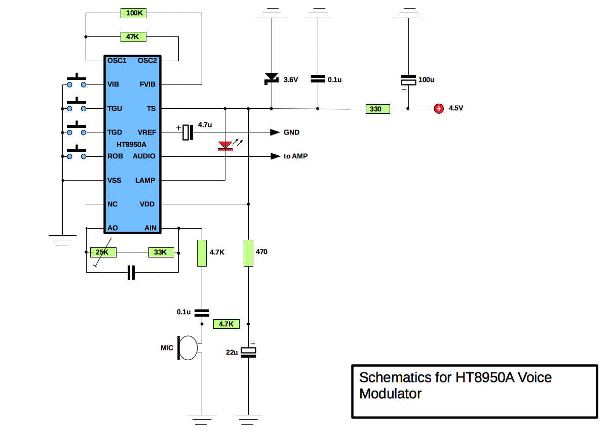
For this project I wanted to deviate from Velleman’s MK171 design and experiment with the HT8950A chip, the heart of the kit. The HT8950A chip from Holtek is a voice modulator that provides two special effects, Vibrato and Robot (pin 2 and 5 respectively). It also provides frequency level shifting enabling the user to shift the frequency up or down (pin 3 and 4 respectively). This is perceived as a higher or lower pitched sound resulting in a ‘Darth Vader’ type of sound when the frequency is shifted two steps lower. More detail on this can be found in the datasheet of the HT8950A. An external LED connected to the LAMP pin (pin 11) changes it’s brightness when the input voice signal changes. Pin 12, the AUDIO, provides the resulting sound that can be amplified.
The chip can be acquired by buying the MK171 kit from Velleman. This kit also provides you with a LM386 amplifier however it is cheaper to buy the HT8950A without the other (generic) components from eBay or Aliexpress. If you do so make sure that your supplier of your choice has sufficient positive feedback. It’s important that you use the HT8950A (DIP-16) and not the HT8950 (DIP-18) which has a very different pin lay-out!
Building it on the breadboard
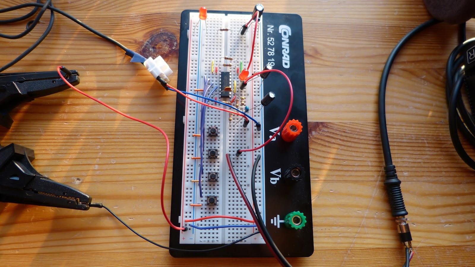
On the datasheet of the HT8950A (page 5 onward) schematics can be found how to connect the chip. The amplifier of the schematic on page 5 or 7 can easily be exchanged for another one of your liking. I’ll probably use the LM386 because it’s cheap and I have several on stock. In order to operate the HT8950A one only needs a couple of generic components (7 resistors, 5 capacitors, an LED and a Zener diode) so building it is not too complicated.
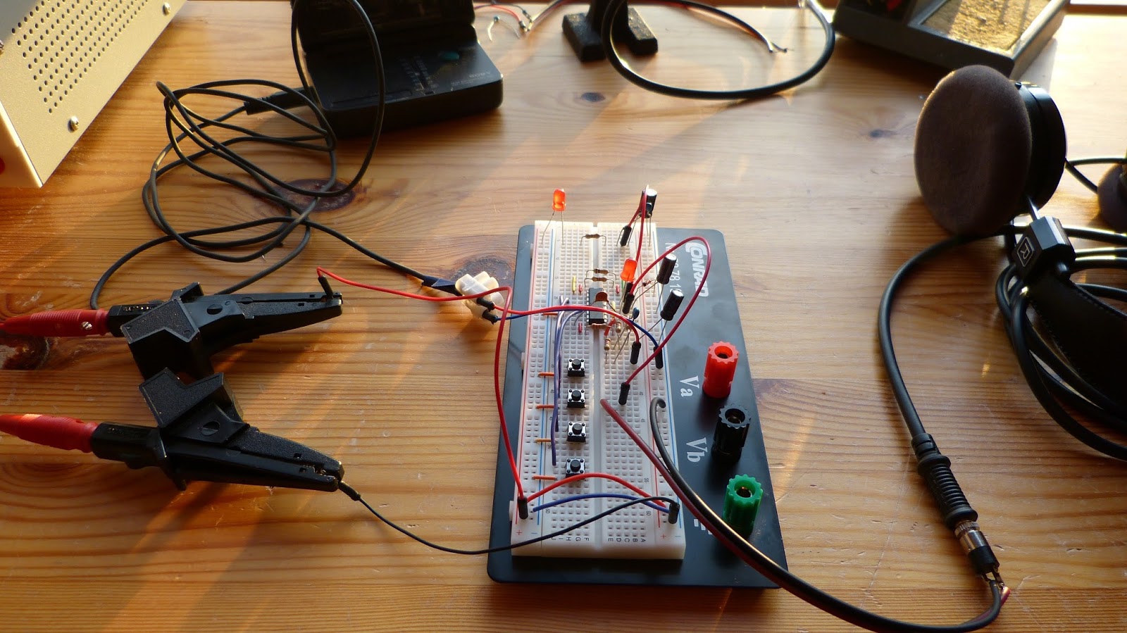
First I built the circuit on the breadboard without an amplifier. The HT8950A actually has it’s own built-in amplifier consequently connecting a small speaker to AUDIO (pin 12) is sufficient to give an audible sound, though barely. Alternatively a headphone can be used. This is especially useful if your roommates start complaining about the weird noise. Later I also connected a homemade amplifier to the circuit (to my roommates despair). The Robot mode sounds good but while testing the frequency level shifting mode a lot of noise became apparent. Placing a capacitor over pin 8 and 9 (AO and AIN respectively) reduces this noise considerably. Optionally a 25K potentiometer can be placed between the 33K resistor and pin 8 to tune the sensitivity of the microphone or any other sound input.
Although I’m rather pleased with the result. I would like to take this experiment a little further. Next I’ll try to further optimize the sound, add the LM386 amplifier and solder the circuit to a perf board. Then I’ll either use the plywood housing that I made for the original version or make a lighter one.
Here are the links to all blog posts I wrote about this chest box:
- Darth Vader voice changer 2.0 (HT8950A) part 1, demonstrates the voice changer on the breadboard: https://homehack.nl/darth-vader-voice-changer-2-0-ht8950a/
- Darth Vader voice changer 2.0 part 2: designing the case: https://homehack.nl/darth-vader-voice-changer-2-0-designing-the-case/
- Homemade Darth Vader Voice Changer 2.0 (work in progress) part 3: https://homehack.nl/homemade-darth-vader-voice-changer-2-0-work-in-progress/
- The Darth Vader chest box part 4: almost finished: https://homehack.nl/the-darth-vader-chest-box-is-almost-finished
- Darth Vader voice changer 2.0 part 5: finished: https://homehack.nl/darth-vader-chest-box-finished/